background image

7

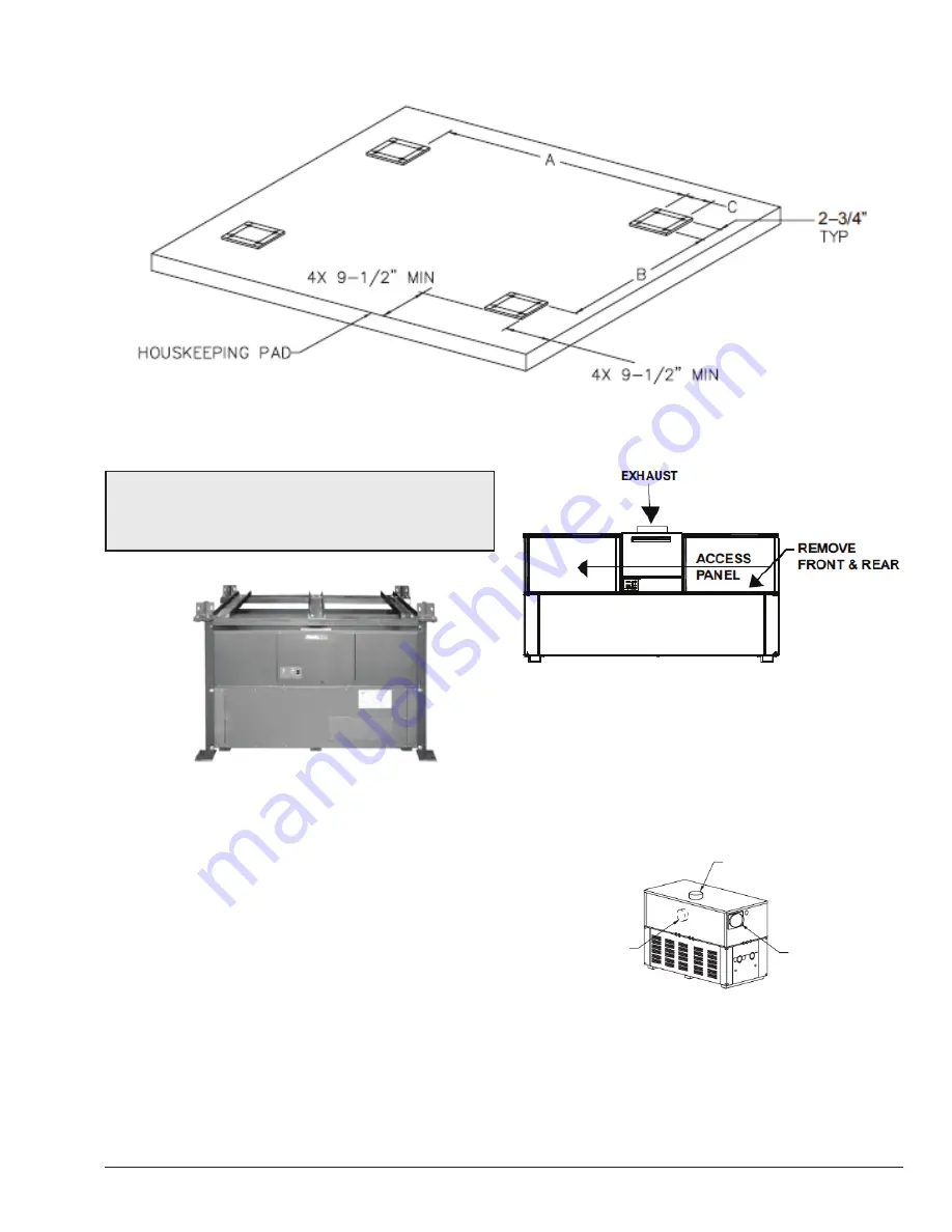
Figure 2. 

SURERACK ANCHORING INFORMATION

NOTE:

 The rack is to be assembled around the bottom 

boiler  first.  Do  not  pre-assemble.  It  is  recommended 

that  the  rack  be  installed  first  prior  to  any  plumbing, 

electrical, venting, or gas hook-up.

Figure 3. 

ASSEMBLE RACK AROUND BOTTOM 

BOILER

INSTALLATION

READ COMPLETELY BEFORE ASSEMBLING RACK.

1.  Identify  the  heater  model  number.  This  information 

is on the rating plate located on the lower right front 

panel. Confirm correct item lengths for the unit to be 

installed. Refer to Table B.

2.  Once  the  unit  is  located  in  its  permanent  position, 

remove the left and right access panels from the front 

and rear of the boiler as shown in Figure 4.

Figure 4. 

FRONT VIEW

3.  Reverse  the  exhaust  vent  panels  to  the  alternate 

locations at rear of the heater on the bottom unit. See 

Figure 5. Refer to the heater I&O manual for detailed 

instructions (P/N: 241663 or 241664). These manuals 

can be found in the document library at www.raypak.

com.

ALTERNATE FLUE 

CONNECTION

FLUE EXHAUST

COMBUSTION AIR 

FILTER (INLET)

Figure 5. 

REAR VIEW

4.  Remove  the  8  plastic  plugs  from  the  lower  boiler 

corners and 8 from the boiler midsections.

Содержание SureRack Kit

Страница 1: ...06 30 22 Replaces 12 09 10 P N 240792 Rev 4 INSTALLATION INSTRUCTION MANUAL SureRack Kit X 3 Restraint Kit FOR HI DELTA MODELS 302 2342 302A 2342A 302B 2342B 302C 2342C AND DELTA LTD MODELS 399 2339 3...

Страница 2: ...o coversheet and X 3 Restraint Bracket Kit Added note The SureRack is designed to connect to the lower unit to provide lateral bracing Raypak cannot support using a SureRack as a platform to elevate a...

Страница 3: ...3 TABLE OF CONTENTS 1 X 1 KIT CONTENTS 4 Anchoring Information 4 2 INSTALLATION 7 3 X 2 ADD ON LEG KIT 9 4 X 3 RESTRAINT BRACKET KIT 10...

Страница 4: ...using a SureRack as a platform to elevate an upper unit with no lower unit 1 X 1 KIT CONTENTS Item Description Qty P N for Sizes 302 902 399 899 P N for Sizes 992 2342 989 2339 Location 1 Leg assembly...

Страница 5: ...5 Figure 1 SURERACK ASSEMBLY...

Страница 6: ...72 011567 402149 109 47 2339 2342 011568 402150 120 81 Item numbers correspond to the numbers listed in Figure 1 on page 5 Table B PARTS LENGTHS FOR SURERACK ASSEMBLIES Anchoring Information For refer...

Страница 7: ...engths for the unit to be installed Refer to Table B 2 Once the unit is located in its permanent position remove the left and right access panels from the front and rear of the boiler as shown in Figu...

Страница 8: ...bottom and midsection of the other three legs See Figure 7 16 total 14 Tighten all the leg bolts after all the attaching bolts are in place 15 If it is required that the legs be bolted to the floor fo...

Страница 9: ...25 Fully tighten all the nuts and bolts on the restraint feet on the support beams and on the cross members Also re tighten the bolts on the bottom of the rack assembly Figure 11 COMPLETED ASSEMBLY X...

Страница 10: ...NC x 2 0 8 550267 ASSEMBLY 1 Place one foot at each corner of the boiler 2 Place one L shaped mounting bracket under the boiler at each corner as shown in Figure 13 3 Insert one 2 bolt and washer thro...

Страница 11: ...THE 3 8 16 X 2 SCREW AT THIS LOCATION ONLY ONE ON EACH CORNER OF THE BOILER FLAT SIDE OF RESTRAINT FOOT FACES FORWARD Figure 13 X 3 RESTRAINT FOOT DETAILS Refer to Table C and Figure 2 in this instru...

Страница 12: ...12 NOTES Raypak Inc 2151 Eastman Avenue Oxnard CA 93030 805 278 5300 www raypak com...

Отзывы: