background image


30

ADJUSTMENT 

THERMOSTATS 


On/Off Models 

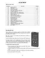
Water heaters with On/Off operation are fitted with 
an AKO adjustable thermostat with the temperature 
sensor located in the inlet side of the header. 
 
This type of control is used where the system load 
is constant, e.g. potable hot water supplied from a 
storage tank or underfloor heating. 
 

To adjust Set Temperature 

a. 

Press the “

À

” button for 5 seconds to display the current ‘Set Point’. 

b. 

Press the “

¿

”or “

À

”buttons to increase or decrease the set point to that required. 

c. 

Press the “

¿

” and “

À

” buttons simultaneously to lock the new setting into the controller, the current 

water temperature will be redisplayed. 


To adjust Parameters 

The thermostat has a number of parameters that are programmed during manufacture (refer to the 
‘AKO Parameter table’ on page 31 for values); advice should be sort from your local Raypak 
representative prior to altering any values other than the set point or the differential. 
 

a. 

Press the “

¿

”and “

À

”buttons simultaneously until ‘C0’ is displayed (approx 10 seconds). 

b. 

Press the “

¿

” or “

À

” buttons to display the parameter that requires setting i.e. C1 (refer to the AKO 

Parameter Table on page 31 for parameter values). 

c. 

Press the “

¿

”and “

À

”buttons simultaneously to display the current value of the parameter selected 

in step b. 

d. 

Press the “

¿

” or “

À

” buttons to alter the value of the parameter. 

e. 

Press the “

¿

”and “

À

”buttons simultaneously to exit the parameter adjustment. The parameter 

selected in step b is redisplayed 

f. 

Press the “

¿

” or “

À

” buttons to select the next parameter that requires setting or if all parameters 

are set until ‘EP’ is displayed. 

g. 

Press the “

¿

”and “

À

”buttons simultaneously to save the setting changes and exit programming. 

 
NOTE: 

1. 

If a button is not pressed within any 25 second period the controller will exit programming mode 
without saving any changes. 

2. 

Failure to exit the programming mode via EP will result in the new settings not being saved 

 
NOTE: If a remote thermostat is used to control the water temperature e.g. a Tankstat, the water 
heater thermostat should be set to a slightly higher temperature than that of the remote thermostat. 
 

Fault Codes 

 
In the event a fault occurs with the thermostat or the temperature sensor a 2-digit code will be 
displayed on the thermostat LED. 
 

Code Fault 

AL 

Temperature below the minimum set point parameter C3 

AH 

Temperature above the maximum set point parameter C2   

EE Memory 

error 

E1 

Temperature sensor set open circuit 


Содержание B0520

Страница 1: ...0 B0770 B0870 This Installation and Operating Instructions Manual is provided with the information for the installation operation and maintenance of your Raypak Heater Please review and follow these p...

Страница 2: ...by the Victorian Building Act 1993 Only a licensed person will give you a Compliance Certificate showing that the work complies with all the relevant standards Only a licensed person will have insuran...

Страница 3: ...ERATION 28 LIGHTING PROCEDURE 28 TO TURN OFF THE WATER HEATER 29 ADJUSTMENT 30 THERMOSTATS 30 BURNER GAS PRESSURE ADJUSTMENT 33 TEMPERATURE RISE 34 FLOW SWITCH 34 HIGH LIMIT 34 AIR PRESSURE SWITCH 35...

Страница 4: ...isolation valve DO NOT use a mobile phone in the vicinity Vacate the area and call your gas supplier or qualified gasfitter NOTE Some gases are heavier than air and it may be necessary to check for ga...

Страница 5: ...WATER INCREASES THE RISK OF SCALD INJURY This water heater can deliver water at temperatures which can cause scalding Check the water temperature before use such as when entering a shower or filling a...

Страница 6: ...le of operating for many trouble free years on most public water supplies Should the installation be in an area where corrosive or hard water is present contact Raypak to ensure that the quality of th...

Страница 7: ...resentative for any further instructions COMPONENTS PROVIDED WITH THE WATER HEATER 1 x 305mm x 60o elbow with grill DO NOT INSTALL OR START UP THIS WATER HEATER IF IT HAS BEEN DAMAGED WITHOUT FIRST CO...

Страница 8: ...water piping electrical conduits trees fences or other equipment etc must not obstruct the front or top of the heater You must be able to read the information on the rating plate Remember you may hav...

Страница 9: ...ue gases from this water heater have a CO2 level of 1 Additional ventilation will be required Ventilation shall be via two permanent openings directly to outside one at an upper level and one at low l...

Страница 10: ...ions where each water heater is individually flued the 300mm diameter flue for each water heater can be run for a total length of 20m with 3 x 90o bends plus the supplied 60o terminal see diagram oppo...

Страница 11: ...er must join the common flue using a 30o swept junction positioned so as to direct the flue gases into the common flue in the direction of discharge The common flue must be sized in accordance with AS...

Страница 12: ...Replace the fan cover assembly in the new direction and replace all screws GAS INLET The pipe work must be cleared of foreign matter before connection and purged before attempting to light the water...

Страница 13: ...fer to the pump selection and pipe size table on page 13 Intermittent pump operation Where pump operation is intermittent a remote thermostat must be fitted in the system and a pump run on timer is re...

Страница 14: ...must use brass or copper olives Use thread sealing tape or approved thread sealant on all fittings Mechanical Hydronic and Process Heating Applications The pressure of the make up supply must be contr...

Страница 15: ...discharge will not cause injury damage or nuisance The drain line must discharge at an outlet or air break not more than 9 metres from the relief valve In locations where water pipes are prone to free...

Страница 16: ...INSTALLLATION 16...

Страница 17: ...INSTALLLATION 17 Typical Installation one water heater one tank...

Страница 18: ...in the diagrams on page 18 A disconnection union must always be provided at the cold water inlet and hot water outlet on the water heater to allow for disconnection of the water heater Each high point...

Страница 19: ...off controls 2 The bypass pipe diameter MUST be the same as the inlet and outlet pipes 3 Select the pipe size between the heater and the system loop main equal to the inlet outlet header connections o...

Страница 20: ...adjacent to and accessible from the water heater refer to AS 5601 5 2 11 A suitable warning label must be affixed to the water heater if there are additional control circuits not isolated by this swit...

Страница 21: ...isolating switch alternatively the water heater power supply may be switched by the auxiliary contacts of the pump contactor refer to diagrams on page 22 THE WATER HEATER MUST NOT OPERATE WITHOUT THE...

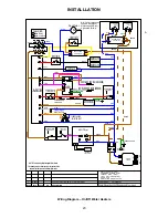
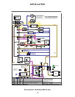
Страница 22: ...INSTALLLATION 22 Wiring diagram Raypak water heater with 415V 3 phase circulator Wiring diagram Raypak Water Heater with 240V Single Phase Circulator...

Страница 23: ...LUE BLUE BLUE BLUE BLUE BLUE Orange GRAY BROWN Update and finalise drawing to current standards 15 05 07 BLUE Red GREEN YELLOW GREEN YELLOW GREEN YELLOW 2 1 AKO T Stat A 11 12 Water Sensor Installed I...

Страница 24: ...BROWN Update and finalise drawing to current standards 15 05 07 BLUE Red GREEN YELLOW GREEN YELLOW GREEN YELLOW A 6 Violet Black BROWN BLUE BLUE BLUE BLUE RAYPAK AUSTRALIA Pty Ltd BROWN BROWN BLUE 1...

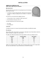
Страница 25: ...t measurement errors the sensor should Be sealed Not painted over Connection The ambient air sensor is connected to terminals B9 and M9 on the RWF40 thermostat Programming When utilising outdoor compe...

Страница 26: ...601 and local authority requirement A power flue if provided must be interlocked with the water heater as required by AS 5601 8 Ensure flammable or combustible materials are not stored near the water...

Страница 27: ...ever be less than 41 C 4 If the heater inlet temperature remains less than 10 C higher than the system loop return temperature and valve A is fully open leave valve A fully open and throttle valve B u...

Страница 28: ...solation valve Never use any tools If the knob will not turn by hand do not try to repair it call a qualified service technician Force or attempted repair may result in a fire or explosion 3 Ensure wa...

Страница 29: ...of the water heater due to poor combustion will result in rapid and severe damage which is not covered by warranty LOCATION OF CONTROLS 1 FLAME FAILURE RESET This is a combination reset button and ind...

Страница 30: ...AKO Parameter Table on page 31 for parameter values c Press the and buttons simultaneously to display the current value of the parameter selected in step b d Press the or buttons to alter the value o...

Страница 31: ...with modulating operation are fitted with an RWF40 adjustable controlling thermostat with the temperature sensor located in the outlet side of the header This type of control is used where the system...

Страница 32: ...ect the next parameter Repeat steps 3 6 until all parameters are set correctly Refer to the RWF40 PARAMETER TABLE below When all parameters are set correctly press the EXIT button to exit programming...

Страница 33: ...water heater Refer to the Lighting Procedure on page 28 4 Adjust the low fire gas pressure to 0 3kPa Natural Gas Models or 1 3kPa propane models by turning the outer regulator screw on the SKP25 actu...

Страница 34: ...by warranty FLOW SWITCH Adjustment Screw The adjustment screw alters the amount of pressure or flow required to activate the micro switch To adjust the setting 1 Loosen the locknut 2 Turn the screw cl...

Страница 35: ...NOTE Ensure the manometer is calibrated prior to connection d Slightly loosen the union between the test point and the tube sensing fan pressure e Undo the Phillips head screw refer to Figure 4 item 1...

Страница 36: ...the spade terminal and connect the wire for the required speed refer to the Fan Speed Table below e Insulate all unused fan connections and cable tie in a safe position FAN SPEED TABLE Fan Speed Wire...

Страница 37: ...should commence operation If the fan does not start up check the fan isolation switch is in the ON position refer to Location Of Controls on page 29 If the fan still does not operate turn off the gas...

Страница 38: ...nd clean pilot assembly s including injector s 5 Clean and re align electrode s and or flame rod s and or thermocouple s 6 Clean main burner injectors and burner bars as required 7 Inspect repair if m...

Страница 39: ...ppliance and its immediate area FIRE TILE REFRACTORY HANDLING CAUTION Ceramic refractories are used in Raypak heaters Please refer to the Material Safety Data Sheet MSDS provided for safe handling of...

Страница 40: ...se 7 The water heater must be sized to supply the hot water demand in accordance with the guidelines in Rheem Water Heater literature WARRANTY EXCLUSIONS 1 REPAIR AND REPLACEMENT WORK WILL BE CARRIED...

Страница 41: ...41 RHEEM SERVICE 131031 WWW RHEEM COM AU Manufactured by Raypak Australia Ph 03 9757 3333 Fax 03 9757 4974 Part No 209130 5 Effective 01 07 2007 Replaces 01 10 2000...

Отзывы: