Raynor 3595RGD 3/4 HP Скачать руководство пользователя страница 18

18

Fiberglass, aluminum or lightweight steel garage doors

WILL REQUIRE

reinforcement BEFORE installation of

door bracket. Contact your door manufacturer for
reinforcement kit.

WARNING

CAUTION

WARNING

WARNING

INSTALLATION STEP 11

Fasten the Door Bracket 

Follow instructions which apply to your door type as
illustrated below or on the following page.

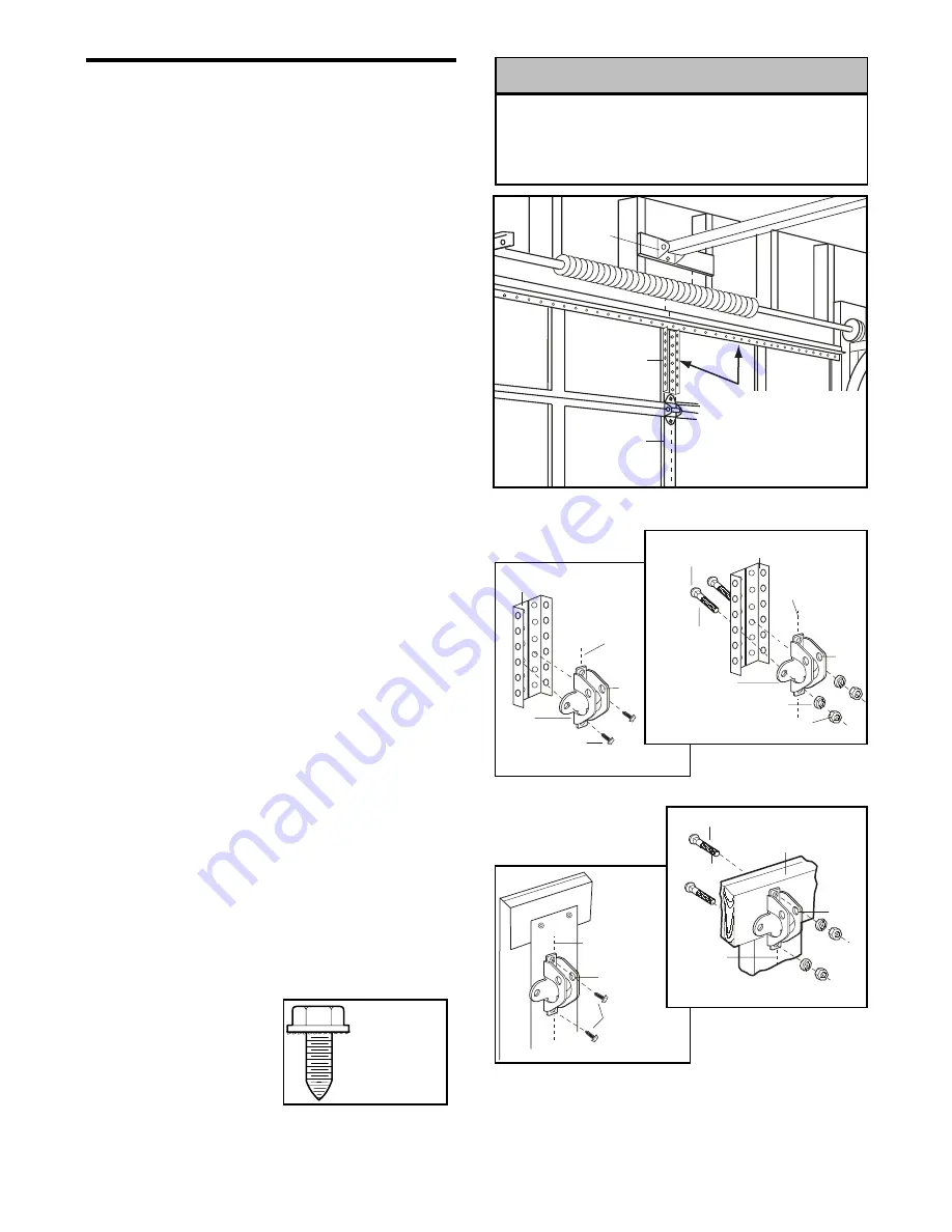
A horizontal reinforcement brace should be long
enough to be secured to two or three vertical
supports. A vertical reinforcement brace should
cover the height of the top panel.

Figure 1 shows one piece of angle iron as the
horizontal brace. For the vertical brace, 2 pieces of
angle iron are used to create a U-shaped support.
The best solution is to check with your garage door
manufacturer for an opener installation door
reinforcement kit.

NOTE:

Many door reinforcement kits provide for

direct attachment of the clevis pin and door arm. In
this case you will not need the door bracket; proceed
to Step 12.

SECTIONAL DOORS

1. Center the door bracket on the previously marked

vertical centerline used for the header bracket
installation. 

N

ote correct UP placement, as

stamped inside the bracket.

2. Position the top edge of the bracket 2"-4" 

(5-10 cm) below the top edge of the door, OR
directly below any structural support across the top
of the door.

3. Mark, drill holes and install as follows, depending

on your door’s construction:

Metal or light weight doors using a vertical angle
iron brace between the door panel support and
the door bracket: 

• Drill 3/16" fastening holes. Secure the door bracket

using the two 1/4"-14x5/8" self-threading screws.
(Figure 2A)

• Alternately, use two 5/16" bolts, lock washers and

nuts (not provided). (Figure 2B)

Metal, insulated or light weight factory reinforced
doors: 

• Drill 3/16" fastening holes. Secure the door bracket

using the self-threading screws. (Figure 3)

Wood Doors:

• Use top and bottom or side to side door bracket

holes. Drill 5/16" holes through the door and
secure bracket with 5/16"x2" carriage bolts, lock
washers and nuts (not provided). (Figure 4)

NOTE: 

The 1/4"-14x5/8"

self-threading screws are
not intended for use on
wood doors.

Vertical
Centerline
of Garage 
Door

Door
Bracket
Location

Header
Bracket

HORIZONTAL AND VERTICAL    
REINFORCEMENT IS NEEDED 
FOR LIGHTWEIGHT GARAGE 
DOORS (FIBERGLASS, 
ALUMINUM, STEEL, DOORS 
WITH GLASS PANEL, ETC.). 
(NOT PROVIDED)

Door
Bracket

Vertical
Centerline 
of Garage Door

UP

Vertical
Reinforcement

Self-Threading
Screw
1/4"-14x5/8"

Self-Threading
Screw
1/4"-14x5/8"

Door
Bracket

Nut
5/16"-18

Bolt
5/16"-18x2"

Lock  Washer
5/16"

UP

Vertical
Reinforcement

(Not Provided)

Vertical
Centerline 
of Garage Door

UP

Self-Threading
Screw
1/4"-14x5/8"

Vertical
Centerline 
of Garage Door

UP

Inside Edge
of Door or
Reinforcement Board

Bolt
5/16"x2"

(Not Provided)

Vertical
Centerline 
of Garage 
Door

Figure 1

Figure 2A

Figure 3

Figure 4

Figure 2B

HARDWARE
SHOWN
ACTUAL SIZE

Содержание 3595RGD 3/4 HP

Страница 1: ...fety materials carefully Fasten the manual near the garage door after installation The door WILL NOT CLOSE unless the Protector System is connected and properly aligned Periodic checks of the opener a...

Страница 2: ...roblem 25 26 Programming 27 28 To add or reprogram a hand held remote control 27 To erase all codes 27 3 Button remotes 27 To add reprogram or change a Keyless Entry PIN 28 Repair Parts 29 30 Rail ass...

Страница 3: ...ement Preparing your garage door Before you begin Disable locks Remove any ropes connected to garage door Complete the following test to make sure your garage door is balanced and is not sticking or b...

Страница 4: ...r 4 SECTIONAL DOOR INSTALLATION Planning Identify the type and height of your garage door Survey your garage area to see if any of the conditions below apply to your installation Additional materials...

Страница 5: ...artons which contain the motor unit and all parts illustrated below Accessories will depend on the model purchased If anything is missing carefully check the packing material Parts may be stuck in the...

Страница 6: ...pener by inserting a 5 16 18x1 2 washered screw through a hole in each side flange and a matching hole in the bracket Complete the connection by inserting the 8 32x3 8 screw through the back flange an...

Страница 7: ...ND FOLLOW ALL INSTALLATION WARNINGS AND INSTRUCTIONS 2 Install garage door opener only on properly balanced and lubricated garage door An improperly balanced door may not reverse when required and cou...

Страница 8: ...l line on the header wall 2 5 cm above the high point This height will provide travel clearance for the top edge of the door To prevent possible SERIOUS INJURY or DEATH Header bracket MUST be RIGIDLY...

Страница 9: ...rage Door Header Wall Garage Door UP CEILING MOUNT ONLY Wall Mounting Holes Optional Wall Mounting Holes The nail hole is for positioning only You must use lag screws to mount the header bracket UP CE...

Страница 10: ...ket Rail HARDWARE SHOWN ACTUAL SIZE INSTALLATION STEP 4 Position the Opener SECTIONAL DOOR ONLY A 2x4 laid flat is convenient for setting an ideal door to rail distance Raise the opener onto a steplad...

Страница 11: ...ntered above the door 7 Remove the 2x4 Operate the door manually If the door hits the rail raise the header bracket 8 Grease the top and underside of the rail surface where the trolley slides with rai...

Страница 12: ...nnect terminals as follows white to white and white red to red NOTE When connecting multiple door controls to the opener twist same color wires together Insert wires into quick connect holes white to...

Страница 13: ...n overhand knot at least 1 2 5 cm from the end of the rope to prevent slipping Thread the other end of the rope through the hole in the release arm of the outer trolley Adjust rope length so the handl...

Страница 14: ...he black line wire to the screw on the brass terminal the white neutral wire to the screw on the silver terminal and the ground wire to the green ground screw The opener must be grounded Reinstall the...

Страница 15: ...talled on the left or right of the door as long as the sun never shines directly into the receiving eye lens The mounting brackets are designed to clip onto the track of sectional garage doors without...

Страница 16: ...will not support the bracket securely wall installation is recommended Wall installation Place the bracket against the wall with curved arms facing the door Be sure there is enough clearance for the s...

Страница 17: ...dily if wiring connections and alignment are correct The sending eye amber indicator light will glow regardless of alignment or obstruction If the green indicator light in the receiving eye is off dim...

Страница 18: ...ollows depending on your door s construction Metal or light weight doors using a vertical angle iron brace between the door panel support and the door bracket Drill 3 16 fastening holes Secure the doo...

Страница 19: ...ty Figure 3 Hole alignment alternative If holes in curved arm are above holes in straight arm disconnect straight arm Cut about 6 15 cm from the solid end Reconnect to trolley with cut end down as sho...

Страница 20: ...Adjustment Step 2 If the door does not close completely Increase down travel Turn the down limit adjustment screw counterclockwise One turn equals 3 7 5 cm of travel If door still won t close complet...

Страница 21: ...Make small adjustments until the door completes a close cycle After each adjustment run the opener through a complete travel cycle Do not increase the force beyond the minimum amount required to clos...

Страница 22: ...un the opener through 3 or 4 complete travel cycles to test adjustment If the unit continues to fail the Safety Reverse Test call for a trained door systems technician IMPORTANT SAFETY CHECK Test the...

Страница 23: ...emote controls and one SAFETY SIGNALTM Keyless Entry System If you purchase a new remote or if you wish to deactivate any remote follow the instructions in the Programming section Activate your opener...

Страница 24: ...to 1 1 2 2 1 2 or 3 1 2 minutes as follows Press and hold the Lock button until the light blinks about 10 seconds A single blink indicates that the timer is reset to 1 1 2 minutes Repeat the procedur...

Страница 25: ...easy to install CARE OF YOUR OPENER LIMIT AND FORCE ADJUSTMENTS Weather conditions may cause some minor changes in door operation requiring some re adjustments particularly during the first year of op...

Страница 26: ...nts to force or travel limits The need for occasional adjustment of the force and limit settings is normal Weather conditions in particular can affect door travel 11 The door reverses for no apparent...

Страница 27: ...ight goes out approximately 6 seconds All previous codes are now erased Reprogram each remote or keyless entry you wish to use 1 Press and release the learn button on the motor unit The learn indicato...

Страница 28: ...y PIN 1 Press the four buttons for your personal entry PIN not the last temporary PIN then press and hold the button The opener light will blink three times Release the button 2 Press the temporary 4...

Страница 29: ...24 Motion detecting door control panel 2 373RGD 3 button remote control 3 10A20 3V2032 Lithium battery 4 29B137 Remote control visor clip 5 41A2828 Emergency release rope handle assy 6 41B4494 1 2 Co...

Страница 30: ...et 8 108D79 Lens 9A 30B530 Capacitor 56uF 9B 30B529 Capacitor 40uF 9C 41A5637 Resistor 10 41A3150 Terminal block w screws 11 81C253 Limit switch drive retainer 12 41A5640 Limit switch assembly KEY PAR...

Страница 31: ...garage door opener from outside by entering a password on a specially designed keyboard Also can add a temporary password for visitors or service persons This temporary password can be limited to a pr...

Страница 32: ...epair which upon receipt by Seller are confirmed to be defective and covered by this limited warranty will be repaired or replaced at Seller s sole option at no cost to you and returned pre paid Defec...

Отзывы: