Raynor 3245RGD 1/3 HP Скачать руководство пользователя страница 2

2

Introduction 2-5

Safety symbol and signal word review  . . . . . . . . . . . . . . . 2

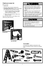
Preparing your garage door  . . . . . . . . . . . . . . . . . . . . . . . 3

Tools needed. . . . . . . . . . . . . . . . . . . . . . . . . . . . . . . . . . . 3

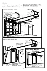
Planning . . . . . . . . . . . . . . . . . . . . . . . . . . . . . . . . . . . . . . 4

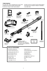
Carton inventory . . . . . . . . . . . . . . . . . . . . . . . . . . . . . . . . 5

Hardware inventory. . . . . . . . . . . . . . . . . . . . . . . . . . . . . . 5

Assembly 6-7

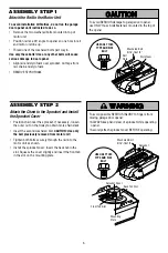
Attach the rail to the motor unit  . . . . . . . . . . . . . . . . . . . . 6

Attach the chain to the sprocket  . . . . . . . . . . . . . . . . . . . . 6

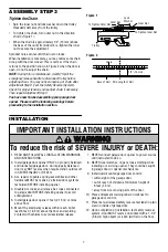
Tighten the chain  . . . . . . . . . . . . . . . . . . . . . . . . . . . . . . . 7

Installation  

7-22

Installation safety instructions  . . . . . . . . . . . . . . . . . . . . . 7

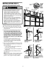
Determine the header bracket location  . . . . . . . . . . . . . . . 8

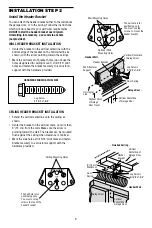
Install the header bracket  . . . . . . . . . . . . . . . . . . . . . . . . . 9

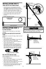
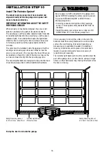
Attach the rail to the header bracket  . . . . . . . . . . . . . . . . 10

Position the opener. . . . . . . . . . . . . . . . . . . . . . . . . . . . . 10

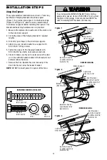
Hang the opener  . . . . . . . . . . . . . . . . . . . . . . . . . . . . . . . 11

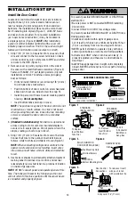
Install the door control  . . . . . . . . . . . . . . . . . . . . . . . . . . 12

Install the light  . . . . . . . . . . . . . . . . . . . . . . . . . . . . . . . . 13

Attach the emergency release rope and handle. . . . . . . . 13

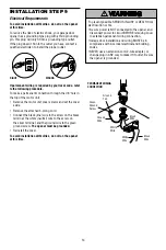
Electrical requirements . . . . . . . . . . . . . . . . . . . . . . . . . . 14

Install the Protector System

®

  . . . . . . . . . . . . . . . . . .  15-18

Fasten the door bracket. . . . . . . . . . . . . . . . . . . . . . .  19-20

Connect the door arm to the trolley  . . . . . . . . . . . . .  21-22

Adjustment 23-25

Adjust the travel limits  . . . . . . . . . . . . . . . . . . . . . . . . . . 23

Adjust the force. . . . . . . . . . . . . . . . . . . . . . . . . . . . . . . . 24

Test the safety reversal system. . . . . . . . . . . . . . . . . . . . 25

Test the Protector System

®

. . . . . . . . . . . . . . . . . . . . . . . 25

Operation 26-30

Operation safety instructions  . . . . . . . . . . . . . . . . . . . . . 26

Using your garage door opener  . . . . . . . . . . . . . . . . . . . 26

Using the wall-mounted door control  . . . . . . . . . . . . . . . 27

To open the door manually . . . . . . . . . . . . . . . . . . . . . . . 27

Care of your opener  . . . . . . . . . . . . . . . . . . . . . . . . . . . . 28

Having a problem?  . . . . . . . . . . . . . . . . . . . . . . . . . . . . . 29

Diagnostic chart  . . . . . . . . . . . . . . . . . . . . . . . . . . . . . . . 30

Programming 31-32

To add or reprogram a hand-held remote control . . . . . . 31

To erase all codes . . . . . . . . . . . . . . . . . . . . . . . . . . . . . . 31

3-Button remotes  . . . . . . . . . . . . . . . . . . . . . . . . . . . . . . 31

To add, reprogram or change 
a Keyless Entry PIN. . . . . . . . . . . . . . . . . . . . . . . . . . . . . 32

Repair Parts 

33-34

Rail assembly parts. . . . . . . . . . . . . . . . . . . . . . . . . . . . . 33

Installation parts . . . . . . . . . . . . . . . . . . . . . . . . . . . . . . . 33

Motor unit assembly parts  . . . . . . . . . . . . . . . . . . . . . . . 34

Accessories 35

Repair Parts and Service 

36

Warranty 36

TABLE OF CONTENTS

When you see these Safety Symbols and Signal Words on 
the following pages, they will alert you to the possibility 
of 

serious injury or death

 if you do not comply with the 

warnings that accompany them. The hazard may come 
from something mechanical or from electric shock. Read 
the warnings carefully.

When you see this Signal Word on the following pages, it 
will alert you to the possibility of damage to your garage 
door and/or the garage door opener if you do not comply 
with the cautionary statements that accompany it. Read 
them carefully.

INTRODUCTION

Safety Symbol and Signal Word Review

This garage door opener has been designed and tested to offer safe service provided it is installed, operated, maintained 
and tested in strict accordance with the instructions and warnings contained in this manual.

Mechanical

Electrical

Содержание 3245RGD 1/3 HP

Страница 1: ...LL NOT CLOSE unless the Protector System is connected and properly aligned Periodic checks of the opener are required to ensure safe operation The model number label is located on the front panel of y...

Страница 2: ...r 28 Having a problem 29 Diagnostic chart 30 Programming 31 32 To add or reprogram a hand held remote control 31 To erase all codes 31 3 Button remotes 31 To add reprogram or change a Keyless Entry PI...

Страница 3: ...lement Preparing your garage door Before you begin Disable locks Remove any ropes connected to garage door Complete the following test to make sure your garage door is balanced and is not sticking or...

Страница 4: ...r is closed Support bracket fastening hardware is required See page 11 Motor Unit FINISHED CEILING Wall Mounted Door Control Extension Spring OR Torsion Spring Header Wall Access Door Safety Reversing...

Страница 5: ...Washer 5 16 4 Screw 6ABx1 1 4 2 Screw 6 32x1 2 Self Threading Screw 1 4 14x5 8 2 Insulated Staples 30 Ring Fastener 3 Drywall Anchors 2 Carriage Bolt 1 4 20x1 2 2 Wing Nut 1 4 20 2 Rope Handle SAFETY...

Страница 6: ...nut on the trolley to obtain more chain slack Insert the second washered bolt CAUTION Use only the bolt previously removed from motor unit Tighten both bolts securely through the rail into the motor...

Страница 7: ...balanced and lubricated garage door An improperly balanced door may NOT reverse when required and could result in SEVERE INJURY or DEATH 3 ALL repairs to cables spring assemblies and other hardware MU...

Страница 8: ...r the top edge of the door NOTE If the total number of inches exceeds the height available in your garage use the maximum height possible or refer to page 9 for ceiling installation To prevent possibl...

Страница 9: ...e ceiling as shown Center the bracket on the vertical mark no more than 6 15 cm from the wall Make sure the arrow is pointing toward the wall The bracket can be mounted ush against the ceiling when cl...

Страница 10: ...s not tall enough Open the door all the way and place a 2x4 laid at on the top section beneath the rail If the top section or panel hits the trolley when you raise the door pull down on the trolley re...

Страница 11: ...line with the header bracket if the bracket is not centered above the door 7 Remove the 2x4 Operate the door manually If the door hits the rail raise the header bracket NOTE DO NOT connect power to op...

Страница 12: ...allowing 1 8 3 mm to protrude above wall surface Position bottom of door control on screw head and slide down to secure Adjust screw for snug t Install top screw with care to avoid cracking plastic ho...

Страница 13: ...he hole in the release arm of the outer trolley Adjust rope length so the handle is 6 feet 1 83 m above the oor Ensure that the rope and handle clear the tops of all vehicles to avoid entanglement Sec...

Страница 14: ...Connect the black line wire to the screw on the brass terminal the white neutral wire to the screw on the silver terminal and the ground wire to the green ground screw The opener must be grounded Rei...

Страница 15: ...eiving eye lens The mounting brackets are designed to clip onto the track of sectional garage doors without additional hardware If it is necessary to mount the units on the wall the brackets must be s...

Страница 16: ...oor Attach brackets to wall with lag screws not provided If using extension brackets or wood blocks adjust right and left assemblies to the same distance out from the mounting surface Make sure all d...

Страница 17: ...ollow the instructions below Cut the end of the safety reversing sensor wire making sure there is enough wire to reach the pre installed wires from the wall Figure 7 Separate the safety reversing sens...

Страница 18: ...orrect wiring between sensors and opener A broken wire 2 If the sending eye indicator light glows steadily but the receiving eye indicator light doesn t Check alignment Check for an open wire to the r...

Страница 19: ...epending on your door s construction Metal or light weight doors using a vertical angle iron brace between the door panel support and the door bracket Drill 3 16 fastening holes Secure the door bracke...

Страница 20: ...he door if required for your installation Refer to the dotted line optional placement drawing HARDWARE SHOWN ACTUAL SIZE Self Threading Screw 1 4 14x5 8 WOOD DOOR METAL DOOR Finished Ceiling HORIZONTA...

Страница 21: ...alignment alternative If holes in curved arm are above holes in straight arm disconnect straight arm Cut about 6 15 cm from the solid end Reconnect to trolley with cut end down as shown Bring arm sec...

Страница 22: ...tton The trolley will travel to the fully closed position Figure 5 Figure 6 Manually close the door and lift the door arm to the trolley The arm should touch the trolley just ahead of the door arm con...

Страница 23: ...ce as explained in Adjustment Step 2 If the door does not close completely Increase down travel Turn the DOWN limit adjustment screw counterclockwise One turn equals 2 5 cm of travel If door still won...

Страница 24: ...by turning the control clockwise Make small adjustments until the door completes a close cycle After each adjustment run the opener through a complete travel cycle Do not increase the force beyond the...

Страница 25: ...bstruction and run the opener through 3 or 4 complete travel cycles to test adjustment If the unit continues to fail the Safety Reverse Test call for a trained door systems technician IMPORTANT SAFETY...

Страница 26: ...trol is activated Bulb size is 100 watts maximum SAFETY SIGNAL light feature Lights will also turn on when someone walks through the open garage door With a Multi Function Door Control this feature ma...

Страница 27: ...on To turn off press and hold the Lock button again for 2 seconds The push bar light will stop ashing The Lock feature will also turn off whenever the learn button on the motor unit panel is activate...

Страница 28: ...tteries DO NOT recharge disassemble heat above 100 C 212 F or incinerate Care of Your Opener LIMIT AND FORCE ADJUSTMENTS Weather conditions may cause some minor changes in door operation requiring som...

Страница 29: ...to force or travel limits The need for occasional adjustment for the force and limit settings is normal Weather conditions in particular can affect door travel Refer to Adjustment Step 1 Adjust the UP...

Страница 30: ...or unit Momentarily short across red and white terminals with jumper wire If motor unit activates replace door control wires Symptom Sending indicator light glows steadily receiving indicator light is...

Страница 31: ...be heard 1 Press and release the learn button on the motor unit The learn indicator light will glow steadily for 30 seconds 2 Within 30 seconds press and hold the button on the hand held remote that...

Страница 32: ...ights will blink once when the PIN has been learned Test by pressing the new PIN then press Enter The door should move To set a temporary PIN You may authorize access by visitors or service people wit...

Страница 33: ...hium battery 4 29B137 Remote control visor clip 5 41A2828 Emergency release rope handle assembly 6 41B4494 1 2 Conductor bell wire white white red 7 41A4353 Header bracket with clevis pin fastener 8 4...

Страница 34: ...ring assembly RPM sensor KEY PART NO NO DESCRIPTION 11 41A5525 25 Cover 12 41A2818 Limit switch drive retainer 13 41D3452 Limit switch assembly 14 41A2822 1 Interrupter cup assembly 15 41C4398A RPM se...

Страница 35: ...Includes visor clip Outside Keylock Opens the garage door automatically from outside when remote control is not handy 8 foot 2 4 m Complete Rail To allow an 8 foot 2 4 m door to open fully 10 foot 3 m...

Страница 36: ...o you THIS LIMITED WARRANTY DOES NOT COVER NON DEFECT DAMAGE DAMAGE CAUSED BY IMPROPER INSTALLATION OPERATION OR CARE INCLUDING BUT NOT LIMITED TO ABUSE MISUSE FAILURE TO PROVIDE REASONABLE AND NECESS...

Отзывы: