Raymarine RMK-10 Скачать руководство пользователя страница 22

6.1 Installation checklist

Installation includes the following activities:

Installation Task

1.

Plan your system.

2. Obtain all required equipment and tools.

3.

Site all equipment.

4.

Route all cables.

5. Drill cable and mounting holes.

6. Make all connections into equipment.

7.

Secure all equipment in place.

8. Power on and test the system.
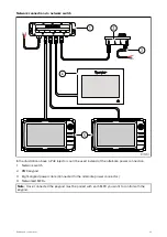
Schematic diagram

A schematic diagram is an essential part of planning any installation. It is also useful for any future
additions or maintenance of the system. The diagram should include:

• Location of all components.

• Connectors, cable types, routes and lengths.

Tools required

Product installation requires the following tools:

Item

Description

Quantity

Power drill

1

Pozidrive screwdriver

1

22

Содержание RMK-10

Страница 1: ...Installation and operation instructions English en US Date 03 2021 Document number 81367 3 2021 Raymarine UK Limited RMK 10 KEYPAD ...

Страница 2: ......

Страница 3: ...o more than three copies of this manual for your own use You may not make any further copies or distribute or use the manual in any other way including without limitation exploiting the manual commercially or giving or selling copies to third parties Software updates Check the Raymarine website for the latest software releases for your product www raymarine com software Product documentation The l...

Страница 4: ......

Страница 5: ...supplied 16 Chapter 4 Product dimensions 17 4 1 Product dimensions 18 Chapter 5 Location requirements 19 5 1 General location requirements 20 5 2 Warnings and cautions 20 Chapter 6 Installation 21 6 1 Installation checklist 22 Schematic diagram 22 Tools required 22 Removing the keypad mat 23 Flush mounting the keypad 24 Surface mounting the keypad 25 Fitting the keypad mat 25 Chapter 7 Cables and ...

Страница 6: ...ad status 40 9 2 PoE troubleshooting 40 9 3 Power up troubleshooting 41 Chapter 10 Maintenance 43 10 1 Service and maintenance 44 10 2 Routine equipment checks 44 10 3 Product cleaning 44 Chapter 11 Technical specification 45 11 1 Technical specification 46 11 2 Compliance 46 Chapter 12 Technical support 47 12 1 Raymarine product support and servicing 48 12 2 Learning resources 49 Chapter 13 Spare...

Страница 7: ...d on unless instructed in this document Caution Power supply protection When installing this product ensure the power source is adequately protected by means of a suitably rated fuse or thermal circuit breaker Water ingress Water ingress disclaimer Although the waterproof rating capacity of this product meets the IPX6 standard water intrusion and subsequent equipment failure may occur if the produ...

Страница 8: ... that this product is compliant with the essential requirements of EMC Directive 2014 30 EU The original Declaration of Conformity certificate may be viewed on the relevant product page at www raymarine com manuals Product disposal Dispose of this product in accordance with the WEEE Directive The Waste Electrical and Electronic Equipment WEEE Directive requires the recycling of waste electrical an...

Страница 9: ...ument was correct at the time it was produced However Raymarine cannot accept liability for any inaccuracies or omissions it may contain In addition our policy of continuous product improvement may change specifications without notice As a result Raymarine cannot accept liability for any differences between the product and this document Please check the Raymarine website www raymarine com to ensur...

Страница 10: ...10 ...

Страница 11: ...Chapter 2 Document and product information Chapter contents 2 1 Document information on page 12 2 2 Product overview on page 12 2 3 Software updates on page 13 Document and product information 11 ...

Страница 12: ...ur product Description Part number Installation and operation instructions 81367 RMK 10 Mounting template 87283 2 2 Product overview The RMK 10 is a Remote Keypad for Raymarine multifunction displays MFD The keypad is a class 1 PoE Power Over Ethernet device and can be powered either using a suitable network connection that is providing PoE or directly using the dedicated Alternate power connector...

Страница 13: ...cific product Important To prevent potential software related issues with your product always follow the relevant update instructions carefully and in the sequence provided If in doubt as to the correct procedure for updating your product software refer to your dealer or Raymarine technical support Caution Installing software updates The software update process is carried out at your own risk Befo...

Страница 14: ...14 ...

Страница 15: ...Chapter 3 Parts supplied Chapter contents 3 1 Parts supplied on page 16 Parts supplied 15 ...

Страница 16: ...10 keypad 2 Landscape keypad mat Note The Landscape keypad mat is only supplied with T70293 3 Portrait keypad mat supplied fitted to the unit 4 Mounting gasket 5 4 x mounting fixings 6 Documentation pack 7 Right angled power cable 2 m 6 6 ft 8 RayNet network cable 2 m 6 6 ft 16 ...

Страница 17: ...Chapter 4 Product dimensions Chapter contents 4 1 Product dimensions on page 18 Product dimensions 17 ...

Страница 18: ...mensions Dimension Measurement A 34 8 mm 1 37 in B 10 5 mm 0 41 in C 28 4 mm 1 12 in D 31 7 mm 1 25 in E 50 7 mm 2 00 in F 80 0 mm 3 15 in G 119 0 mm 4 69 in H 133 0 mm 5 24 in I 41 0 mm 1 61 in J 55 0 mm 2 17 in 18 ...

Страница 19: ...Chapter 5 Location requirements Chapter contents 5 1 General location requirements on page 20 5 2 Warnings and cautions on page 20 Location requirements 19 ...

Страница 20: ...lectrical interference the product should be mounted far enough away from any equipment that may cause interference such as engines motors generators radio transmitters receivers and cables carrying high power Magnetic compass refer to the Compass safe distance section in this document for advice on maintaining a suitable distance between this product and any compasses on your vessel Power to keep...

Страница 21: ...Chapter 6 Installation Chapter contents 6 1 Installation checklist on page 22 Installation 21 ...

Страница 22: ...uipment 7 Secure all equipment in place 8 Power on and test the system Schematic diagram A schematic diagram is an essential part of planning any installation It is also useful for any future additions or maintenance of the system The diagram should include Location of all components Connectors cable types routes and lengths Tools required Product installation requires the following tools Item Des...

Страница 23: ...t must be removed Tip To help prevent scratching the product cover the tip of your screwdriver blade with a small piece of insulation tape 1 Using a thin flat bladed screwdriver insert the tip of the screwdriver into the gap between the edge of the keypad mat and the keypad housing at a location between locking tabs 2 Gently lever the keypad mat away from the keypad to release the keypad mat Take ...

Страница 24: ...f the cut out area 6 Using a suitable saw cut along the inside edge of the cut out line 7 Using a Router follow the Flush mount rebate line to cut out a rebate to the specified rebate depth as indicated on the template 8 Ensure that the unit fits into the removed area and then remove rough edges 9 Place the supplied gasket onto the rear of the keypad ensuring the mounting holes are aligned 10 Conn...

Страница 25: ...gh edges 8 Place the supplied gasket onto the rear of the keypad ensuring the mounting holes are aligned 9 Connect the relevant cables to the unit 10 Secure using the fixings provided Note The appropriate tightening torque and drill bit size to use depends on the thickness of the mounting surface and the type of material it is made from Note The supplied gasket provides a seal between the unit and...

Страница 26: ...nd of the keypad that has 2 notches to accept the tabs 3 Close the opposite end of the keypad mat into the keypad ensuring that the tab slides into the notch provided Push all of the tabs on the longer sides into their notches you should hear a click as each tab engages 26 ...

Страница 27: ...les and connections Chapter contents 7 1 General cabling guidance on page 28 7 2 Connections overview on page 29 7 3 Alternate power connection on page 29 7 4 Keypad connections on page 30 Cables and connections 27 ...

Страница 28: ...t all cables from physical damage and exposure to heat Use trunking or conduit where possible Do NOT run cables through bilges or doorways or close to moving or hot objects Secure cables in place using cable clips or cable ties Coil any excess cable and tie it out of the way Where a cable passes through an exposed bulkhead or deckhead use a suitable watertight feed through Do NOT run cables near t...

Страница 29: ...ss on the connectors due to the extra weight of the cable 7 2 Connections overview 1 Alternate power connector 2 Network PoE connector The alternate power connector is required when connecting to a network which does not support Power over Ethernet PoE The alternate power connector must be connected directly to a power supply Note Do not connect the alternate power connector to a SeaTalk ng networ...

Страница 30: ...negative battery terminal connected to the vessel s ground Floating with neither battery terminal connected to the vessel s ground Warning Positive ground systems Do not connect this unit to a system which has positive grounding 7 4 Keypad connections The keypad can be connected directly to a multifunction display s MFDs network connector or via a network switch Multiple keypads can be connected t...

Страница 31: ...pad 4 Right angled power cable Connected to the alternate power connector Direct MFD connection with PoE injector 1 MFD 2 RMK keypad 3 RayNet to RJ45 network cable A62360 A80151 or A80159 4 PoE injector power supply 12 24 V dc 5 PoE injector R32141 Cables and connections 31 ...

Страница 32: ...MFD providing PoE 2 RMK keypad 3 RayNet network cable with suppression ferrite fitted 4 Networked MFDs Note The keypad can be used to control networked MFDs even when the MFD it is connected to is switched off as long as the MFD still has power supplied to it 32 ...

Страница 33: ...e used instead of the alternate power connection 1 Network switch 2 RMK keypad 3 Right angled power cable Connected to the alternate power connector 4 Networked MFDs Note Once connected the keypad must be paired with each MFD you want to control with the keypad Cables and connections 33 ...

Страница 34: ...34 ...

Страница 35: ...Chapter 8 Operation Chapter contents 8 1 Keypad controls on page 36 8 2 Pairing the keypad on page 37 Operation 35 ...

Страница 36: ...ain to place a waypoint Press and hold to place a Man Overboard MOB marker at your current position 9 Standby Auto press to disengage integrated autopilot press and hold to activate Auto mode on integrated autopilot 10 Power see table below Configuration Display State Momentary press Press and hold Off Not applicable Not applicable Single MFD On Open Shortcuts page Power off put into Standby All d...

Страница 37: ...lication page and or to switch the active display With multiple displays connected and or a multiple application page displayed Cycle sequence 1 Press the Active button to enter switch mode 2 Use the Rotary control to cycle through the available panes and or displays The keypad will cycle through displays in the order in which they were paired On multi application pages the and buttons can be used...

Страница 38: ...for approximately 6 seconds The keypad will sound a triple beep to signify it is now unpaired Determining the active display You can determine which display is currently active 1 Press the Active button The Active pop up is displayed on the screen or pane that is active 2 Press the Active button again to close the Active pop up The active display remains the same 38 ...

Страница 39: ...Chapter 9 System checks and troubleshooting Chapter contents 9 1 Keypad status on page 40 9 2 PoE troubleshooting on page 40 9 3 Power up troubleshooting on page 41 System checks and troubleshooting 39 ...

Страница 40: ... experiencing connection issues with the remote keypad when powering the device via PoE consider using the keypad s dedicated power connector to supply the power to the device Possible causes for connection issues are Low or inconsistent voltage at the power supply to the MFD Inadequate power or data cabling If multiple devices are powered via PoE from the MFD the power allocation for the PoE devi...

Страница 41: ... 4 Check the vessel s battery voltage and the condition of the battery terminals and power supply cables ensuring connections are secure clean and free from corrosion Replace if necessary 5 With the product under load using a multi meter check for high voltage drop across all connectors fuses etc and replace if necessary Incorrect power connection The power supply may be wired incorrectly ensure t...

Страница 42: ...42 ...

Страница 43: ...Chapter 10 Maintenance Chapter contents 10 1 Service and maintenance on page 44 10 2 Routine equipment checks on page 44 10 3 Product cleaning on page 44 Maintenance 43 ...

Страница 44: ...erform the following routine checks on a regular basis to ensure the correct and reliable operation of your equipment Examine all cables for signs of damage or wear and tear Check that all cables are securely connected 10 3 Product cleaning Best cleaning practices When cleaning products Switch off power supply Use a clean damp cloth to wipe clean Do NOT use abrasive acidic ammonia solvent or other...

Страница 45: ...Chapter 11 Technical specification Chapter contents 11 1 Technical specification on page 46 11 2 Compliance on page 46 Technical specification 45 ...

Страница 46: ...vironmental specification Operating temperature 25 ºC to 55 ºC 13 ºF to 131 ºF Storage temperature 30 ºC to 70 ºC 22 ºF to 158 ºF Relative humidity Maximum 93 Waterproof rating IPx6 IPx7 Wired connections Network PoE 1 x RayNet 10 100 Mb s connector Alternate power 1 x Power connector SeaTalkng style connector 11 2 Compliance The product has been tested to the relevant sections of the standards li...

Страница 47: ...Chapter 12 Technical support Chapter contents 12 1 Raymarine product support and servicing on page 48 12 2 Learning resources on page 49 Technical support 47 ...

Страница 48: ...cific E Mail emea service raymarine com Tel 44 0 1329 246 932 United States US E Mail rm usrepair flir com Tel 1 603 324 7900 Web support Please visit the Support area of the Raymarine website for Manuals and Documents http www raymarine com manuals Technical support forum http forum raymarine com Software updates http www raymarine com software Worldwide support United Kingdom UK EMEA and Asia Pa...

Страница 49: ... your products Video tutorials Raymarine official channel on YouTube YouTube LightHouse 3 tips and tricks Raymarine website Video Gallery Raymarine website Note Viewing the videos requires a device with an Internet connection Some videos are only available in English Training courses Raymarine regularly runs a range of in depth training courses to help you make the most of your products Visit the ...

Страница 50: ...50 ...

Страница 51: ...Chapter 13 Spares and accessories Chapter contents 13 1 Keypad spares and accessories on page 52 Spares and accessories 51 ...

Страница 52: ...s 2 Right angle RayNet connection cable with a straight RayNet female socket on one end and a right angle RayNet female socket on the other end Suitable for connecting at 90 right angle to a device for installations where space is limited 3 RayNet cable puller 5 pack 4 RayNet to RayNet right angle coupler adapter Suitable for connecting RayNet cables at 90 right angle to devices for installations ...

Страница 53: ...RJ45 socket on the other end along with a locking gland for a watertight fit 3 Adapter cable with a RayNet male plug on one end and an RJ45 SeaTalkhs waterproof male plug on the other end 4 Adapter cable with a RayNet male plug on one end and an RJ45 SeaTalkhs male plug on the other end 5 Adapter cable with a RayNet female socket on one end and an RJ45 SeaTalkhs waterproof male plug on the other e...

Страница 54: ......

Страница 55: ...diagnostics 40 LightHouse 3 Tips and Tricks 49 M Maintenance 44 N Network connections 30 Network examples 30 P Pairing 37 Parts supplied 16 PoE connection 29 PoE specification 46 Power connection 29 Power consumption 46 Power specification 46 Power troubleshooting 41 Product dimensions 18 Product documentation 12 Product information 12 Product recycling WEEE 8 Product support 48 R RayNet cables 52...

Страница 56: ...W Warranty 48 Water ingress 46 WEEE Directive 8 ...

Страница 57: ......

Страница 58: ...Raymarine Marine House Cartwright Drive Fareham Hampshire PO15 5RJ United Kingdom Tel 44 0 1329 246 700 www raymarine com a brand by ...

Отзывы: