background image

4-7

Technical Description

4.2

4.2

4.2

4.2

4.2 Handset Circuit

Handset Circuit

Handset Circuit

Handset Circuit

Handset Circuit

4.2.1 Outline

4.2.1 Outline

4.2.1 Outline

4.2.1 Outline

4.2.1 Outline

The handset is connected to the cradle to communicate control data for
various functions, such as transmission/reception of voice signals on the
handset, all key operations, LCD display, lighting by LED, monitor control
of the cradle, etc.

4.2.2 Circuit Makeup

4.2.2 Circuit Makeup

4.2.2 Circuit Makeup

4.2.2 Circuit Makeup

4.2.2 Circuit Makeup

The circuit consists of the following components:
• Power supply system circuit

Digital 5V Voltage Regulator (IC701)
Analog 5V Voltage Regulator (IC702)
Analog 9V Voltage Regulator (IC714)

• Single Chip CPU (IC706)
• LCD Display Controller/Driver (IC709)
• LED Driver Circuit (IC710)
• Electronically-controlled Volume (IC716)

4.2.3 Power Supply System

4.2.3 Power Supply System

4.2.3 Power Supply System

4.2.3 Power Supply System

4.2.3 Power Supply System

The input voltage of the main supply power is +13.6V. The internal operation
voltages for the respective applications are as follows:
• +9V by the voltage regulator (IC714) for LCD lighting
• +5V by the voltage regulator (D5V, IC701) for a digital voltage
• +5V by the voltage regulator (A5V, IC702) for an analog voltage
• +5V (VTH) from emitter follower (Q703) for working bias voltage for the

voice signals

4.2.4 CPU

4.2.4 CPU

4.2.4 CPU

4.2.4 CPU

4.2.4 CPU

The CPU is an 8-bit, single-chip microcomputer 

µ

PD789026 (IC706).

4.2.5 Controller Driver for LCD display

4.2.5 Controller Driver for LCD display

4.2.5 Controller Driver for LCD display

4.2.5 Controller Driver for LCD display

4.2.5 Controller Driver for LCD display

The PCF2113DH/F4 (IC709) is a LCD controller driver used to indicate
alphanumeric characters and symbols.

4.2.6 LED Driver Circuit

4.2.6 LED Driver Circuit

4.2.6 LED Driver Circuit

4.2.6 LED Driver Circuit

4.2.6 LED Driver Circuit

The TB62715 FN (IC710) makes a 4-stage dimming control for the LEDs
(D704–D707) and the LCD backlight, and also turns on/off the keypad
LEDs (D708–D720).

Содержание RAY230E

Страница 1: ...RAY230 RAY230E Fixed Mount VHF Radio Owner s Handbook Document number R49006_1 Date May 2001...

Страница 2: ......

Страница 3: ...C Rules Operation is subject to the conditions that this device does not cause harmful interference Changes or modifications to this equipment not expressly approved in writing by Raymarine Incorporat...

Страница 4: ...or a Station License If your vessel does not require a license you may obtain an MMSI by contacting either BoatUS www boatus com or MariTEL www maritelusa com Once obtained you can program the MMSI nu...

Страница 5: ...censes in your area You can then program the MMSI number into your RAY230E using the Menu Operation described in this handbook If your region does not permit you to program the MMSI number yourself yo...

Страница 6: ...m people located at least three feet 91 cm from the Base Station transceiver and Handsets Adjustments or Repair Adjustments or Repair Adjustments or Repair Adjustments or Repair Adjustments or Repair...

Страница 7: ...vii Declaration of Conformity goes here...

Страница 8: ...designator as defined by the ITU ITU International Telecommunications Union LCD Liquid Crystal Display Memory Scan Scans only user selected memory channels MMSI Maritime Mobile Service Identity a num...

Страница 9: ...alkAuxiliary Junction Box 2 6 2 4 5 Antenna Connections 2 7 2 4 6 Antenna Mounting Suggestions 2 8 2 4 7 Grounding 2 8 SECTION 3 OPERATIONS SECTION 3 OPERATIONS SECTION 3 OPERATIONS SECTION 3 OPERATIO...

Страница 10: ...4 3 5 26 3 Receiving an Individual Call 3 36 3 5 26 4 Receiving a Group Call 3 37 3 5 26 5 Transmitting anAll Ships Call 3 38 3 5 26 6 Receiving anAll Ships Call 3 39 3 5 26 7 Transmitting a Distress...

Страница 11: ...code All Channel Receiver 4 4 4 1 2 7 DSC Decoding Channel 70 Receiver 4 4 4 1 3 Transmitter Section 4 4 4 1 3 1 IDCCircuit 4 4 4 1 3 2 BufferDriverAmplifier 4 4 4 1 3 3 APC Circuit 4 4 4 1 3 4 ATIS D...

Страница 12: ...ter All Channel Receiver 5 4 5 3 2 Local Frequency Adjustment Channel 70 Receiver 5 4 5 3 3 ModulationAdjustment Transmitter 5 4 5 3 4 Output PowerAdjustment Transmitter 5 4 5 3 5 RF SensitivityAdjust...

Страница 13: ...Safety calls 1 2 1 2 1 2 1 2 1 2 Equipment Features Equipment Features Equipment Features Equipment Features Equipment Features The RAY230 RAY230E is designed and manufactured to provide ease of oper...

Страница 14: ...that automatically selects 16 or 9 as the Priority Channel when the radio is turned on Dedicated key for changing the Priority Channel 16 9 Exclusive weather alert feature when in monitor mode Exclus...

Страница 15: ...t Supplied Thefollowingisalist ofmaterials suppliedwiththe RAY230andRAY230E Description Description Description Description Description Part No Part No Part No Part No Part No Base Station Transceiver...

Страница 16: ...cured behind the transceiver to allow for proper cable connections to the rear panel connectors The transceiver should be located as near as possible to the power source The selected location should b...

Страница 17: ...dimensions are shown in inches and millimeters 84 3 31 110 4 33 25 98 65 2 56 70 2 76 114 4 49 Base Station Transceiver Base Station Transceiver Base Station Transceiver Base Station Transceiver Base...

Страница 18: ...o Connects to Connects to Connects to RED Power Ship s 13 2 VDC power BLACK Power YELLOW Hailer Hailer Horn speaker GREEN Hailer WHITE NMEA Input from position source GPS BLACK NMEA LORAN The RED powe...

Страница 19: ...o the negative ground of the power source Should the power connections be inadvertently reversed the unit will not power up but no damage will occur Simply check the polarity with a VOM Voltage Ohm Me...

Страница 20: ...o the SeaTalk auxiliary junction box described in the following section Note All return connections must be tied to a common ground reference 2 4 4 Using the SeaTalk Auxiliary Junction Box 2 4 4 Using...

Страница 21: ...run to avoid excessive losses in power output If the antenna RF connector is likely to be exposed to the marine environment a protective coating of grease Dow Corning DC 4 or similar can be applied to...

Страница 22: ...xial cable designed for the least amount of power loss over the entire cable length Keep the coaxial cable between the radio and antenna as short as possible but remember to maintain the recommended 3...

Страница 23: ...0E can transmit and receive on all available International and US Marine VHF radiotelephone channels There are channels that are FCC approved but may only be used by authorized stations for specific p...

Страница 24: ...in the SQ bar graph on the LCD display will increase or decrease accordingly This key is also used as a scroll key for changing the channel number and other settings as described below VOL UP DOWN key...

Страница 25: ...in Section 3 5 21 3 CELL key 3 CELL key 3 CELL key 3 CELL key 3 CELL key This key inputs the number 3 When an alphanumeric response is appropriate each press of this key alternately inputs the charact...

Страница 26: ...hannel For the RAY230E European model this operation is valid only in US frequency mode 7 D L key 7 D L key 7 D L key 7 D L key 7 D L key This key inputs the number 7 When an alphanumeric response is...

Страница 27: ...he FOG key initiates the Fog Alert mode which enables a Hailer Horn speaker to sound several types of automatic or manual alert tones ENT MENU key ENT MENU key ENT MENU key ENT MENU key ENT MENU key T...

Страница 28: ...so that it can receive any incoming messages To begin transmitting again release the PTT and depress again DISTRESS switch DISTRESS switch DISTRESS switch DISTRESS switch DISTRESS switch This switch i...

Страница 29: ...layed when the International frequency group is selected 1W indicator 1W indicator 1W indicator 1W indicator 1W indicator Displayed when the transmission power of 1W is selected with the 9 1 25 key or...

Страница 30: ...sion 3 3 1 RAY230 US Version 3 3 1 RAY230 US Version 3 3 1 RAY230 US Version 3 3 1 RAY230 US Version 1 1 1 1 1 Selecting the Frequency Mode Selecting the Frequency Mode Selecting the Frequency Mode Se...

Страница 31: ...adle enabling you to listen to radio reception from the external speaker 13 13 13 13 13 Intercom Function between Handsets Intercom Function between Handsets Intercom Function between Handsets Interco...

Страница 32: ...group can be scanned using the Memory Channel Scan function 6 6 6 6 6 Priority Channel Operation Priority Channel Operation Priority Channel Operation Priority Channel Operation Priority Channel Opera...

Страница 33: ...between Handsets Intercom Function between Handsets Intercom Function between Handsets The Intercom function is available when two or more handsets are connected 17 17 17 17 17 Reduced Receiving Sensi...

Страница 34: ...3 12 Operations 3 4 3 4 3 4 3 4 3 4 Equipment Connections Equipment Connections Equipment Connections Equipment Connections Equipment Connections...

Страница 35: ...l then be in a standby power condition the radio circuitry does not yet have power 2 Press the 16 9 key on any handset The full system is powered ON Note If the main power supply switch is OFF the han...

Страница 36: ...olume set with the knob 3 5 3 Setting the Squelch 3 5 3 Setting the Squelch 3 5 3 Setting the Squelch 3 5 3 Setting the Squelch 3 5 3 Setting the Squelch The squelch adjustment enables you to quiet th...

Страница 37: ...elected in the previous group as long as that number is present in the new group If a channel number is absent in the destination group the new channel will be the previous number plus 1 When returnin...

Страница 38: ...ll be the previous number plus 1 When returning to the previous frequency group the channel returns to its original number if the channel has not been changed If the channel has been changed that numb...

Страница 39: ...onds UsingtheNumericKeypad To select a channel input the desired number on the keypad For 5 seconds the channel number flashes on the LCD display If the ENT key is pressed during this 5 second interva...

Страница 40: ...state except the Distress Call shifts operation to the Priority Channel While using the Priority Channel pressing the 16 key or the CLR key returns operation to the Working Channel 3 5 12 Multi Call...

Страница 41: ...eted 3 5 13 Channel Memory 3 5 13 Channel Memory 3 5 13 Channel Memory 3 5 13 Channel Memory 3 5 13 Channel Memory Channels that are stored in memory in the same group can be scanned using the Memory...

Страница 42: ...E to reduce the receiving sensitivity in high traffic areas to decrease unwanted reception This is also known as local mode To start Sensitivity Reduction press the FUNC key followed by the 7 D L key...

Страница 43: ...5 18 Fog Alert Siren Mode 3 5 18 Fog Alert Siren Mode 3 5 18 Fog Alert Siren Mode The Fog Alert Siren operation enables the unit to use a Hailer Horn speaker as a fog horn siren in one of four differ...

Страница 44: ...interrupted and radio operation is given priority Channel 70 is always monitored for incoming DSC calls Making a call To make a cellular phone call remove the handset from the cradle hook and press t...

Страница 45: ...only one handset is installed the operation is cancelled and an error alert sounds Note The station number can be changed to any name up to a length of 9 letters using the Menu operation For the detai...

Страница 46: ...the calling station appear on the dot matrix display once every second To answer the call press the FUNC key followed by the 0 IC key The calling tone ceases and the message CONNECTappears in the dot...

Страница 47: ...eiving and transmitting Digital Selective Calling DSC functions Using Memory Scan This function is available only when at least one channel has been stored in memory Press the FUNC key followed by the...

Страница 48: ...CLR key or the PTTswitch If Dual Watch mode is initiated at Channel 70 the operation is cancelled and an error alert sounds Tri WatchforUSModelRAY230 In Tri Watch Mode the RAY230 operates on the Work...

Страница 49: ...Tri Watch mode at the current channel press the MON key the CLR key or the PTT switch If Tri Watch mode is initiated at Channel 70 the operation is cancelled and an error alert tone sounds 3 5 23 Prio...

Страница 50: ...OFF Hook Operation disabled Operation disabled Operation possible 3 Higher ranked Handset is taken Off Hook while a lower ranked Handset is Off Hook Handset 1 Handset 2 Handset 3 On Hook OFF Hook OFF...

Страница 51: ...ited Operation disabled In cases 5 and 6 above limited operation means the handset can talk on the Intercom adjust the sound volume and make a Distress Call HandsetDisplay The dot matrix display indic...

Страница 52: ...minute monitor time at power up all the position fields are set to 9 s and the time fields are set to 8 s An error alert tone sounds to urge manual entry see Section 3 5 30 3 2 and the NMEA indicator...

Страница 53: ...sively for Channel 70 so that even if receiving under normal operation the unit can quickly switch over to Channel 70 upon receiving a DSC signal When the DSC signal is received the unit performs the...

Страница 54: ...to select the method for inputting the MMSI number either from the Phonebook or manually Press ENT 4 Select the MMSI number BYPHONEBOOK Scroll with the SQ UP DOWN keys select the name associated with...

Страница 55: ...idual Calls Pressing the SQ UP DOWN will scroll you through the simplex channels usable for this operation Response If a response is received after pressing the PTT switch a receive confirmation messa...

Страница 56: ...setup Channel 16 is automatically assigned for communications To cancel the call press and hold the CLR key for 4 seconds To make an Individual Call to Shore Station ship to shore 1 Press the INDV ke...

Страница 57: ...o press the PTT switch 6 Press PTT to transmit If PTT is not pressed within 15 seconds of the prompt appearing operation returns to the state before the call ENT With manual input MMSI number would be...

Страница 58: ...dual Call When an Individual Call is received the DSC indicator flashes INd appears on the 7 segment display and the DSC Received Alert is sounded On the dot matrix display appears the message RECEIVE...

Страница 59: ...5 26 4 Receiving a Group Call When a Group Call is received the DSC indicator flashes INd appears on the 7 segment display and the DSC ReceivedAlert is sounded On the dot matrix display appears the m...

Страница 60: ...6 5 Transmitting an All Ships Call 3 5 26 5 Transmitting an All Ships Call 3 5 26 5 Transmitting an All Ships Call TheAll Ships Call is classified in two categories Safety Call and Urgency Call To sen...

Страница 61: ...communication are stored in EEPROM If CLR is pressed the radio reverts to the mode before receiving the URGENCY Call and the contents are stored in EEPROM When a SAFETY call is received the DSC Recei...

Страница 62: ...r is displayed On the dot matrix display a countdown message appears prompting you to hold the DISTRESS key for 4 seconds 2 After the countdown has completed release the DISTRESS key The unit is switc...

Страница 63: ...ign one of eleven distress types to the call to provide the potential rescuing station additional information if time and circumstances permit The Nature of the distress call can be selected using the...

Страница 64: ...you wish to attach scroll through the list with the SQ UP DOWN keys When the appropriate message is displayed press the ENT key On the dot matrix display a message appears prompting you to hold the DI...

Страница 65: ...sponse is received the DSC indicator flashes and the DSC Distress alert is sounded The LCD scrolls a message that the DISTRESS has been acknowledged along with the sending station s MMSI number The me...

Страница 66: ...d RECEIVED DISTRESS the type of distress the MMSI number the transmitting time the latitude and longitude of the transmitting station The DSC Distress Alert and the displayed message continue until ei...

Страница 67: ...cribed below 1 Key Click This sound is made when a handset key is pressed In the On Hook state the sound emits from the external speaker in the Off Hook state the sound emits from the handset speaker...

Страница 68: ...receiving a call using the Intercom function when selected through the Menu operation If Off Hook the sound emits from the handset if On Hook the sound emits from the external speaker at a low volume...

Страница 69: ...13 Siren 2 Siren Sound Select this sound option under Siren in the Menu operation While in Fog Siren mode pressing and releasing the PTT switch emits a continuous siren sound from the Hailer Horn spea...

Страница 70: ...n and press the ENT key to enter that particular menu item To exit the Menu operation press and hold the CLR key for 3 seconds FUNC MENU Function Function Function Function Function Purpose Purpose Pu...

Страница 71: ...ing five items with the SQ UP DOWN key or wait as they are automatically displayed at 3 second intervals in the following order 1 Latitude 4 UTC Data Y M D 2 Longitude 5 Position source GPS LORAN etc...

Страница 72: ...1 Press the FUNC key followed by the MENU key to initiate the Menu operation 2 Select NAVSTAT and press the ENTkey The 7 segment display shows dSC and the dot matrix display shows L L ENT The DSC Main...

Страница 73: ...select the nature of the distress that will be included with the call 1 As described in section 3 5 30 3 DSC Operation above select the DSC operation NATURE 2 Press the ENT key to initiate the proces...

Страница 74: ...K e y s K e y s K e y s K e y s Action Action Action Action Action 0 9 keys Changes the flashing numeric value see step 3 then advances to the next digit s place ENT key Advances the flashing subject...

Страница 75: ...press 5 press 7 press SQ UP DOWN press ENT press 7 press ENT press 2 press ENT press ENT Flashing Flashing Flashing Flashing Flashing Flashing Flashing Flashing Flashing Flashing Flashing Flashing Fl...

Страница 76: ...automatic ship to shore calling 1 As described in section 3 5 30 3 DSC Operation above select the DSC operation PHNBOOK 2 Press the ENT key to initiate the process The 7 segment display shows Phb and...

Страница 77: ...ugh 9 The currently selected location is indicated by a flashing character Pressing a numeric key enters that value then advances to the next digit s place To go back by 1 digit press the CLR key 3 To...

Страница 78: ...Press the ENT key and operation returns operation to the mode before the Menu operation began If the list has no stations entered the message PHNBOOK IS EMPTY HOLD DOWN CLR KEY is displayed Press and...

Страница 79: ...the list use the SQ UP DOWN key to select DELETE and press the ENT key If no station has yet been registered the message PHNBOOK IS EMPTY is displayed Note Pressing and holding the CLR key for 3 secon...

Страница 80: ...l characters so that they all display a ENT ON 1 8 press 0 ENT ENT 7 PQRS 2 ABC ENT REPEAT ENT ENT To DELETE mode Flashing Flashing Flashing Flashing Flashing Flashing If the maximum 20 stations are a...

Страница 81: ...PHNBOOK IS EMPTYHOLDDOWNCLRKEYisdisplayed PressandholdtheCLRkey for 3 seconds to exit Menu mode 3 5 30 3 4 Modifying the MMSI Group Number 3 5 30 3 4 Modifying the MMSI Group Number 3 5 30 3 4 Modifyi...

Страница 82: ...Press ENT to register the group and exit the Menu operation To exit without registering press SQ UP DOWN until DEL N is displayed Press the ENT key and operation returns to mode before the Menu opera...

Страница 83: ...between the following INTRCM selects the Intercom setting MYMMSI selects the MMSI number for this unit SIREN selects the Fog Alert siren setting 4 Select the desired operation and press the ENT key t...

Страница 84: ...to submit the entry and proceed to the next place To go back by 1 digit press the CLR key 6 After entering all the desired characters press the ENT key The message RING 1 is now displayed prompting y...

Страница 85: ...be disabled and the programming must be done by your distributor Note This is a one time operation Once the MMSI number has been programmed you will not be able to change it Until the MMSI number is p...

Страница 86: ...ey The message ENT ACCEPT CLR EXIT scrolls across the display 6 Press the ENT key to submit the number The message ENTER MMSI NO AGAIN is displayed 7 Press ENT The nine underscore placeholders appear...

Страница 87: ...select the siren tone 1 SelecttheSIRENfunctionasdescribedaboveinSection3 5 30 4Setting Operation RAY230 2 Press the ENT key The 7 segment display shows Sir the dot matrix display indicates CODENC1 an...

Страница 88: ...g Siren Mode Operating Siren in Fog Siren Mode Operating Siren in Fog Siren Mode Operating Siren in Fog Siren Mode CODENC1 Hi Lo Press and release PTT switch to emit continous sound Press PTT again to...

Страница 89: ...NU key to initiate the Menu mode Mn is shown on the 7 segment display and NAVSTAT appears on the dot matrix display 2 Press the SQ UP DOWN key to select SETTING 3 Press the ENT key The message SET app...

Страница 90: ...this unit was purchased to be used in such a region this function will be disabled and the programming must be done by your distributor Note This is a one time operation Once the ATIS number has been...

Страница 91: ...to exit the Menu mode and try again from step 1 10 Press ENT to verify The message ENT STORE CLR EXIT is displayed 11 Press ENT one last time to register the ATIS number in memory Operation returns to...

Страница 92: ...3 70 Operations Flashing Flashing Flashing ENT ENT Input last 9 digits of ATIS number using numeric keypad ENT ENT ENT re enter ATIS No ENT ENT...

Страница 93: ...Tri Watch state in the US mode To change the monitored channel 1 Per the description in section 3 5 30 8 Setting Operation above select TRI 2 Press the ENT key TrI appears on the 7 segment display and...

Страница 94: ...the dot matrix 3 Press the SQ UP DOWN key to toggle between ATIS ON and ATIS OFF 4 After selecting the desired operation press the ENT key 5 If the setting is acceptable press the ENT key to confirm...

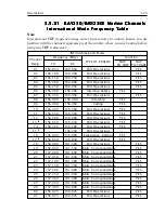
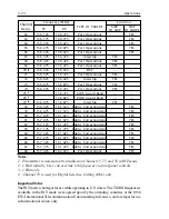
Страница 95: ...ort Operations YES 06 156 300 156 300 Intership Safety YES 07 156 350 160 950 Port Operations YES 08 156 400 156 400 Intership YES 09 156 450 156 450 Calling YES 10 156 500 156 500 Port Operations YES...

Страница 96: ...156 975 161 575 Public Correspondence YES 80 157 025 161 625 Public Correspondence YES 81 157 075 161 675 Public Correspondence YES 82 157 125 161 725 Public Correspondence YES 83 157 175 161 775 Pub...

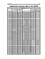
Страница 97: ...2 2 2 2 156 650 156 650 Navigation Bridge to Bridge YES 14 156 700 156 700 Port Operation YES 15 1 1 1 1 1 156 750 Environmental 16 156 800 156 800 Emergency Calling YES 17 3 3 3 3 3 156 850 156 850...

Страница 98: ...ES 79 156 975 156 975 Commercial YES 80 157 025 157 025 Commercial YES 81 4 4 4 4 4 157 075 157 075 Coast Guard YES 82 4 4 4 4 4 157 125 157 125 Coast Guard YES 83 157 175 157 175 Coast Guard YES 84 1...

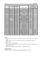
Страница 99: ...l 16 156 800 156 800 Emergency Calling YES 17 3 3 3 3 3 156 850 156 850 State Controlled YES 18 156 900 156 900 Commercial YES 19 156 950 156 950 Commercial YES 20 157 000 157 000 Port Operations YES...

Страница 100: ...ES 83 157 175 157 175 Coast Guard YES 84 157 225 161 825 Marine Operator YES 85 157 275 161 875 Marine Operator YES 86 157 325 161 925 Marine Operator YES 87 157 375 161 975 Marine Operator YES 88 157...

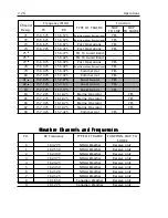
Страница 101: ...4 Not for use by general public Requires special authorization from the U S Coast Guard or under private land mobile license 5 Channel 70 is used for Digital Selective Calling DSC only ImportantNotice...

Страница 102: ...3 80 Operations...

Страница 103: ...29 Q30 and Q331 remains off until the power switch is pressed on the handset At that time the full system is operational 4 1 2 Receiver Section 4 1 2 Receiver Section 4 1 2 Receiver Section 4 1 2 Rece...

Страница 104: ...e desired frequency by 21 6 MHz The 1st local oscillator signal is fed to the 1st mixer Q19 after being amplified by the buffer amplifier Q14 2 FirstIntermediateFrequency 1stIF The 1st IF signal of 21...

Страница 105: ...a frequency of 139 625 MHz The signal is fed to the mixer Q22 via the buffer amplifier Q25 2 1st IF The 1st IF signal of 16 9 MHz supplied via the crystal filter F3 is amplified by the 1st IF amplifie...

Страница 106: ...ircuit Circuit Circuit Circuit After pre emphasis of 6 dB oct in the IDC circuit IC6 the microphone DSC andATIS signals from the control system are supplied to an amplitude limiting circuit Then the s...

Страница 107: ...t the requirement for high speed response by accelerating the rise characteristic at the time of transmission reception changeover and frequency changeover The detection circuit IC5 enables the PLL un...

Страница 108: ...ationalamplifier IC319 IC321 transmits a low impedance AF signal between the base station and the handset 4 1 6 2 Digital I O 4 1 6 2 Digital I O 4 1 6 2 Digital I O 4 1 6 2 Digital I O 4 1 6 2 Digita...

Страница 109: ...em 4 2 3 Power Supply System 4 2 3 Power Supply System The input voltage of the main supply power is 13 6V The internal operation voltages for the respective applications are as follows 9V by the volt...

Страница 110: ...call and monitors the calling voice signal 4 3 2 Power Supply System 4 3 2 Power Supply System 4 3 2 Power Supply System 4 3 2 Power Supply System 4 3 2 Power Supply System 13 6 VDC is supplied as th...

Страница 111: ...FMHum Noiselevel Less than 40 dB below audio Audio Distortion Less than 10 at 1 kHz for 3 kHz deviation Spurious Hamonic Attenuated at least 43 10 log Po below rated radiated carrier Emissions power...

Страница 112: ...at 50 C for 8 hours 4 4 4 Radio Dimensions 4 4 4 Radio Dimensions 4 4 4 Radio Dimensions 4 4 4 Radio Dimensions 4 4 4 Radio Dimensions Base Station Transceiver Height 2 63inches 67mm Width 8 98inches...

Страница 113: ...rt Department Monday to Friday 8 15 AM to 5 00 PM Eastern Standard Time Our Technical Support Specialists are available to answer installation operation and troubleshooting questions about your Raymar...

Страница 114: ...ned from your authorized dealer or contact RaymarineLimited Anchorage Park Portsmouth Hampshire England PO3 5TD Tel 44 0 2392693611 Fax 44 0 2392694642 Or visit Raymarine World Wide Website www raymar...

Страница 115: ...nspect the radio case and antenna for any physical damage 5 3 5 3 5 3 5 3 5 3 Alignment Alignment Alignment Alignment Alignment This transceiver is completely aligned at the factory and does not requi...

Страница 116: ...2 Set the radio on Channel 16 and adjust trimmer capacitor TC2 on the RF PCB for the desired frequency 139 625 MHz 100Hz 5 3 3 Modulation Adjustment Transmitter 5 3 3 Modulation Adjustment Transmitter...

Страница 117: ...itivity Adjustment CH 70 5 3 6 RF Sensitivity Adjustment CH 70 5 3 6 RF Sensitivity Adjustment CH 70 5 3 6 RF Sensitivity Adjustment CH 70 5 3 6 RF Sensitivity Adjustment CH 70 Receiver Receiver Recei...

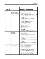
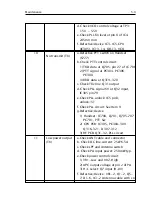
Страница 118: ...sible Cause Possible Cause 1 a 10 amp fuse in power line open b Check Power SW and Relay RL1 c Check SW circuit as follows 1 Q26 input voltage 0 7V ON 2 5v line IC306 out at CPU PCB 3 R166 open 4 D18...

Страница 119: ...ins 7 8 17 of IC315 5 AF level Buff amp at pin 1 of IC319 321 b Defective device CPU IC305 IC310 IC315 IC319 321 Q302 304 Flex cable and connector 5 a Check 5V regulator of IC804 b Check AF level on P...

Страница 120: ...z Xtal OSC b Defective device ANT SW diode D1 2 BPF tracking Vcp PLL circuit Q14 Q16 20 Q30 D9 D11 16 8 a Check SQ circuit on RF PCB and CPU PCB as follows 1 Busy1 noise output pin8 of J2 pin14 of IC7...

Страница 121: ...t Q32 input IC305 pin79 e Check PLL unlock IC5 pin3 unlock 51 f Check PLL circuit See Item 9 g Defective device 1 Handset IC708 Q701 Q705 707 PC701 PTT Sw 2 CPU PCB IC305 PC304 309 Q316 321 D307 312 3...

Страница 122: ...SW IC315 and analog SW IC311 on CPU PCB e Check VCOf Defective device 1 Handset Mic IC704 705 C717 2 CPU PCB IC311 IC315 IC319 321 CPU IC305 3 RF PCB IC6 VR3 VCO 13 a Check Relay RL301 Make Talk Brea...

Страница 123: ...9 182 206 Ceramic Chip Capacitor 8pF 50V 6 C80 101 110 129 176 202 Ceramic Chip Capacitor 10pF 50V 1 C82 Ceramic Chip Capacitor 12pF 50V 2 C76 136 Ceramic Chip Capacitor 15pF 50V 1 C31 Ceramic Chip Ca...

Страница 124: ...c Chip Capacitor 33pF 200V 1 C10 Ceramic Chip Capacitor 15pF 200V 3 C7 11 13 Ceramic Chip Capacitor 33pF 200V 3 C8 9 10 ChipTantalumElectrolyticCapacitor 0 22uF 35V 1 C165 ChipTantalumElectrolyticCapa...

Страница 125: ...33 61 84 117 158 Chip Resistor 15W 1 16W 1 R83 Chip Resistor 220W 1 16W 3 R43 44 49 54 56 62 111 112 113 143 144 145 151 154 Chip Resistor 330W 1 16W 2 R9 89 Chip Resistor 470W 1 16W 2 R11 107 Chip R...

Страница 126: ...r 56kW 1 16W 2 R95 130 Chip Resistor 100kW 1 16W 2 R14 57 63 90 91 98 99 100 119 121 128 156 163 Chip Resistor 150kW 1 16W 2 R114 155 Chip Resistor 220kW 1 16W 6 R18 23 73 79 92 127 Chip Resistor 270k...

Страница 127: ...or 680pF 50V 1 C738 Ceramic Chip Capacitor 1000pF 50V 15 C734 739 741 742 743 744 745 746 747 748 749 750 751 752 753 Ceramic Chip Capacitor 3900pF 50V 1 C737 Ceramic Chip Capacitor 4700pF 50V 1 C726...

Страница 128: ...or 15kW 1 16W 2 R719 753 Chip Resistor 22kW 1 16W 9 R702 711 722 723 724 727 746 747 748 Chip Resistor 33kW 1 16W 1 R715 Chip Resistor 36kW 1 16W 2 R703 713 Chip Resistor 47kW 1 16W 3 R725 741 745 Chi...

Страница 129: ...r 8pin 3 J503 504 505 Connector 3pin 1 J506 Connector 4pin 1 J507 Connector 26pin 1 J508 FFC26pin 1 W509 CTRLAssembly PCB IC 24LC16BT I SN 1 IC322 M30800FCFP 1 IC305 M62363FP 1 IC313 MSM7512BGS VK 2 I...

Страница 130: ...apacitor 220pF 50V 1 C353 Ceramic Chip Capacitor 1000pF 50V 12 C304 327 331 359 361 362 370 371 372 373 376 422 Ceramic Chip Capacitor 1500pF 50V 1 C348 Ceramic Chip Capacitor 2200pF 50V 3 C379 384 38...

Страница 131: ...41 Resistor 330W 1 16W 3 R375 383 402 Resistor 390W 1 16W 2 R356 382 Resistor 470W 1 16W 3 R388 400 412 Resistor 560W 1 16W 3 R387 399 411 Resistor 1kW 1 16W 3 R337 352 364 Resistor 1 5kW 1 16W 1 R439...

Страница 132: ...esistor 47kW 1 16W 1 R313 Rank F 1 Resistor 22W 1 10W 1 R357 Resistor 27W 1 10W 1 R358 Miscellaneous 6 Pin Connector 1 J301 10 Pin Connector 1 J302 20 Pin Connector 1 J303 16 Pin Connector 1 J304 26 P...

Страница 133: ...15pF 50V 3 C915 916 917 Capacitor 18pF 50V 1 C912 Capacitor 1000pF 50V 5 C909 910 911 919 922 Resistor Resistor 100W 1 16W 1 R908 Resistor 470W 1 16W 1 R904 Resistor 560W 1 16W 1 R906 Resistor 2 2kW...

Страница 134: ...6 12 Parts List and Drawings 6 2 6 2 6 2 6 2 6 2 RAY230 ASSEMBLY DRAWING RAY230 ASSEMBLY DRAWING RAY230 ASSEMBLY DRAWING RAY230 ASSEMBLY DRAWING RAY230 ASSEMBLY DRAWING...

Страница 135: ...6 13 Parts List and Drawings 6 3 6 3 6 3 6 3 6 3 BLOCK DIAGRAM BLOCK DIAGRAM BLOCK DIAGRAM BLOCK DIAGRAM BLOCK DIAGRAM...

Страница 136: ...6 14 Parts List and Drawings 6 4 6 4 6 4 6 4 6 4 RAY230 PCB LAYOUT RAY230 PCB LAYOUT RAY230 PCB LAYOUT RAY230 PCB LAYOUT RAY230 PCB LAYOUT...

Страница 137: ...6 15 Parts List and Drawings 6 5 6 5 6 5 6 5 6 5 RAY230 WIRING DIAGRAM RAY230 WIRING DIAGRAM RAY230 WIRING DIAGRAM RAY230 WIRING DIAGRAM RAY230 WIRING DIAGRAM...

Страница 138: ...6 16 Parts List and Drawings...

Страница 139: ...nel 16 is used for distress and safety purposes only Use VHF Channel 70 only for Digital Selective Calling DSC It may be used for general purpose calling using DSC Your cooperation in not using Channe...

Страница 140: ...rt or leave a foreign port to dock in a U S port Your radio license is not transferable If you sell your boat request the FCC to cancel your station license If you replace your radio you do not need t...

Страница 141: ...ncy Calling Monitoring Intership Safety U S Coast Guard Navigation Port Operation Noncommercial Commercial Marine Operator State Control Environmental Weather USAGE GUIDE USAGE GUIDE USAGE GUIDE USAGE...

Страница 142: ...t be broadcast Calling Channel 16 Working Channel If you wish to establish communications with another station And you know which working channel the station is monitoring Then initiate the call direc...

Страница 143: ...ions employ a second receiver so that they can monitor a working channel and channel 16 simultaneously Intership Safety Channel 6 Vessels Any Use Communicating navigational and weather warnings to oth...

Страница 144: ...ift to channel 22 as directed Navigation Channel 13 Vessels Any Use Safety Communications pertaining to the maneuvering of vessels or the directing of vessel movements Ship to ship and secondarily shi...

Страница 145: ...rence Seaway and designated major ports Noncommercial BoatOperations Channels 19 68 69 71 72 78 Vessels Recreational boats and any others not used primarily for commercial transport Use Communications...

Страница 146: ...unications Recreational boats are not permitted to use these channels Channel 88 not available on Great Lakes and St Lawrence Seaway MarineOperator Channels 24 25 26 27 28 84 85 86 87 88 Vessels Any U...

Страница 147: ...nd coast stations associated with state and local governments Environmental Channel 15 Vessels Any receive only Use Broadcast of information concerning the environmental conditions in which vessels op...

Страница 148: ...Vessels Any Use Continuous weather information from NOAA National Oceanic and Atmospheric Administration Between One way broadcast from NOAA to any interested parties Comments Receive only You are no...

Страница 149: ...assist in spelling out similar sounding or unfamiliar words radiotelephone users employ the international phonetic alphabet Phonetic Alphabet A ALPHA B BRA VO C CHARLIE D DELTA E ECHO F FOX TROT G GOL...

Страница 150: ...7 12 Appendix...
Отзывы: