Raymarine GVM400 Скачать руководство пользователя страница 7

Chapter 1: Important information

Warning: Product installation and
operation

This product must be installed and operated in
accordance with the instructions provided. Failure to
do so could result in personal injury, damage to your
boat and/or poor product performance.

Warning: Potential ignition source

This product is NOT approved for use in
hazardous/flammable atmospheres. Do NOT install in
a hazardous/flammable atmosphere (such as in an
engine room or near fuel tanks).

Warning: High voltages

This product contains high voltages. Do NOT remove
any covers or otherwise attempt to access internal
components, unless specifically instructed in this
document.

Warning: Product grounding

Before applying power to this product, ensure it has
been correctly grounded, in accordance with the
instructions in this guide.

Warning: Switch off power supply

Ensure the boat’s power supply is switched OFF
before starting to install this product. Do NOT connect
or disconnect equipment with the power switched on,
unless instructed in this document.

EMC installation guidelines

Raymarine equipment and accessories conform to the appropriate
Electromagnetic Compatibility (EMC) regulations, to minimize
electromagnetic interference between equipment and minimize the
effect such interference could have on the performance of your
system

Correct installation is required to ensure that EMC performance is
not compromised.

For

optimum

EMC performance we recommend that wherever

possible:

• Raymarine equipment and cables connected to it are:

– At least 1 m (3 ft) from any equipment transmitting or cables

carrying radio signals e.g. VHF radios, cables and antennas.
In the case of SSB radios, the distance should be increased
to 7 ft (2 m).

– More than 2 m (7 ft) from the path of a radar beam. A radar

beam can normally be assumed to spread 20 degrees above
and below the radiating element.

• The product is supplied from a separate battery from that used

for engine start. This is important to prevent erratic behavior
and data loss which can occur if the engine start does not have
a separate battery.

• Raymarine specified cables are used.

Important information

7

Содержание GVM400

Страница 1: ...GVM400 video module Installation instructions...

Страница 2: ......

Страница 3: ...mpany names referenced herein are used for identification only and are the property of their respective owners This product is protected by patents design patents patents pending or design patents pen...

Страница 4: ......

Страница 5: ...d 12 2 2 Power cables 12 2 3 Entertainment system example 13 2 4 Dimensions 15 Chapter 3 Cables and connections 17 3 1 GVM video module connections 18 3 2 Thermal camera connection 20 Chapter 4 Locati...

Страница 6: ...6 GVM400 Installation instructions...

Страница 7: ...ipment with the power switched on unless instructed in this document EMC installation guidelines Raymarine equipment and accessories conform to the appropriate Electromagnetic Compatibility EMC regula...

Страница 8: ...ferrite MUST always be attached to the cable near the Raymarine unit Product disposal Dispose of this product in accordance with the WEEE Directive The Waste Electrical and Electronic Equipment WEEE...

Страница 9: ...Series system operating instructions quick reference 86126 G Series system user reference handbook 81276 Glass Bridge monitors user guide 81324 G Series compact keyboard 81316 G Series command center...

Страница 10: ...10 GVM400 Installation instructions...

Страница 11: ...er 2 Planning the installation Chapter contents 2 1 Parts supplied on page 12 2 2 Power cables on page 12 2 3 Entertainment system example on page 13 2 4 Dimensions on page 15 Planning the installatio...

Страница 12: ...is not supplied with a power cable Power cables must be of the appropriate gauge Cable length Power supply voltage Cable gauge AWM Cable gauge mm2 12 volts 20 0 52 0 to 5 m 0 to 16 4 ft 24 volts 20 0...

Страница 13: ...4 GHI 5 JK L 6 MNO ACTIVE WPTS MOB DAT A MENU PAGE 0 2 ABC 3 DEF 1 CANCEL ST ANDBY DODGE PIL OT OK RANGE OUT IN ENTER 1 3 5 10 D11795 1 S Video A V A V SeaTalkhs SeaTalkhs SeaT alkng SeaTalk ng SeaT...

Страница 14: ...eyboard 4 Satellite TV 5 Wireless base station 6 Video camera 7 Video camera with audio connection 8 GVM video module 9 SeaTalkhs switch 10 GPM processor unit 11 Audio output to vessel s audio system...

Страница 15: ...2 4 Dimensions D11883 1 170 mm 6 7 in 237 mm 9 33 in 56 mm 2 2 in Planning the installation 15...

Страница 16: ...16 GVM400 Installation instructions...

Страница 17: ...Chapter 3 Cables and connections Chapter contents 3 1 GVM video module connections on page 18 3 2 Thermal camera connection on page 20 Cables and connections 17...

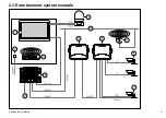
Страница 18: ...3 1 GVM video module connections D11820 1 SeaT alkhs 1 3 7 4 2 8 6 5 18 GVM400 Installation instructions...

Страница 19: ...le no further video devices may be connected to that GVM unit The G Series system supports a maximum of 3 GVM video modules providing a total of 12 video inputs less if connecting S Video or thermal c...

Страница 20: ...e the optional Joystick Control Unit JCU with the camera this must also be connected to the SeaTalkhs switch A composite video connection is also required between the camera and a GVM video module D11...

Страница 21: ...tware To check your software version select MENU System Diagnostics Software Services Unit Info App Version Refer to your dealer or the Raymarine website www raymarine com for latest software versions...

Страница 22: ...s connected to 5 Repeat Steps 1 to 4 for each GVM video module in your system that has a thermal camera connected to it Note You can only connect 1 thermal camera to each GVM video module in your G Se...

Страница 23: ...Chapter 4 Location and mounting Chapter contents 4 1 Location requirements on page 24 4 2 Mounting arrangement on page 24 Location and mounting 23...

Страница 24: ...mportant to consider a number of factors Do NOT install near sources of heat or vibration for example an engine Install below decks in a dry area Must be mounted on a vertical surface Sides and top mu...

Страница 25: ...Chapter 5 Troubleshooting Chapter contents 5 1 Video troubleshooting on page 26 Troubleshooting 25...

Страница 26: ...o Input 1 on the GVM video module is working The GVM video module has been previously connected to a thermal camera If you no longer want to connect a thermal camera to the GVM video module you must r...

Страница 27: ...sible causes 4 flashing red LEDs Flash write error 6 flashing red LEDs Video stopped 7 flashing red LEDs Video error 8 flashing red LEDs possibly followed by flashing amber Hardware read failure Troub...

Страница 28: ...28 GVM400 Installation instructions...

Страница 29: ...Chapter 6 Technical specification Chapter contents 6 1 Technical specification on page 30 Technical specification 29...

Страница 30: ...55 C 5 F to 131 F Non operating temperature 25 C to 70 C 13 F to 158 F Relative humidity limit 80 Water protection drip resistant when mounted vertically Storage conditions for packaged unit Temperat...

Страница 31: ...Chapter 7 Spare parts Chapter contents 7 1 GVM400 video module spares on page 32 Spare parts 31...

Страница 32: ...7 1 GVM400 video module spares The following parts are available as spares Cable Part number Notes GVM Connector Cover R08276 GVM install pack R08318 32 GVM400 Installation instructions...

Страница 33: ......

Страница 34: ...www raymarine com...

Отзывы: