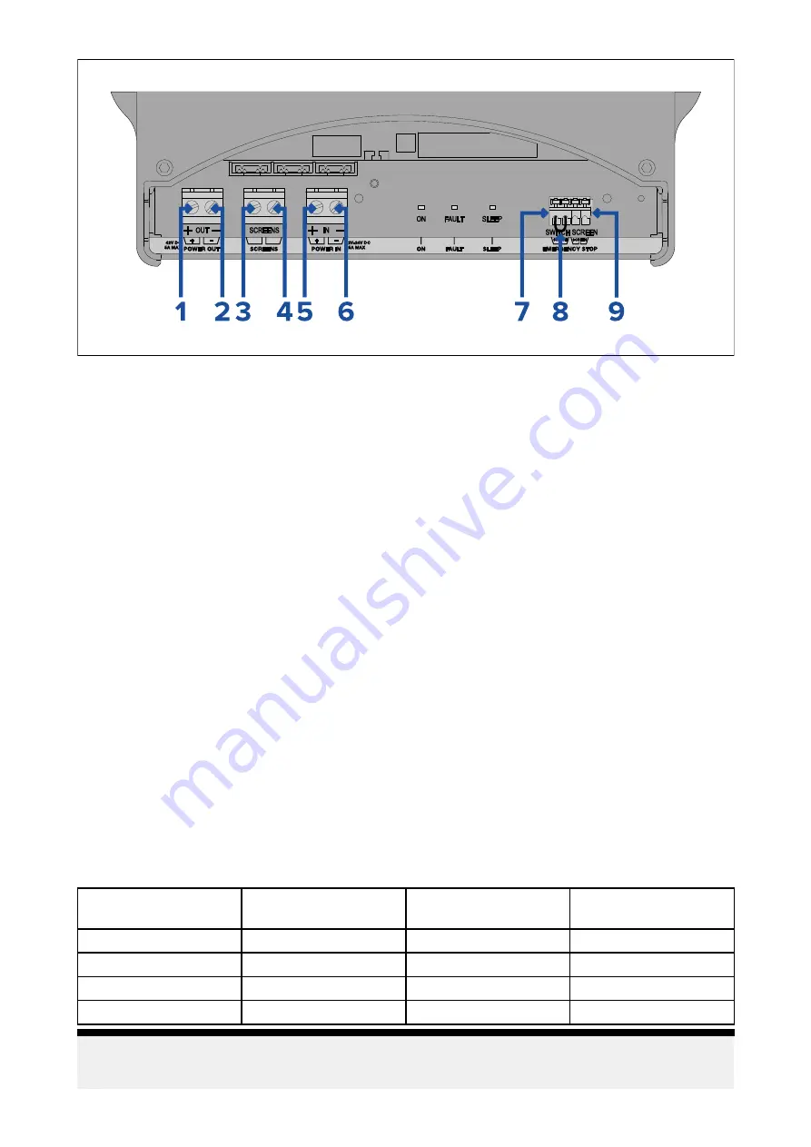
1.
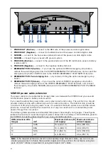
POWER OUT (Positive)
— connect to the RED wire of the power and data digital cable.
2.
POWER OUT (Negative)
— connect to the BLACK wire of the power and data digital cable.
3.
SCREEN
— connect to the bare screen (drain) strands of the power and data digital cable.
4.
SCREEN
— connect to your vessel's RF ground system.
5.
POWER IN (Positive)
— connect to the positive terminal of the DC distribution panel or battery
isolator switch.
6.
POWER IN (Negative)
— connect to the negative battery terminal.
7.
EMERGENCY STOP (Switch)
— if you have the optional VCM100 emergency stop button,
remove the wire bridging link from the VCM100 EMERGENCY STOP terminals, and connect the
emergency stop button SWITCH wire to the VCM100 EMERGENCY STOP SWITCH terminal.
8.
EMERGENCY STOP wire bridging link
— only remove if fitting the optional emergency stop
button.
9.
EMERGENCY STOP (Screen)
— if you have the optional VCM100 emergency stop button,
remove the wire bridging link from the VCM100 EMERGENCY STOP terminals, and connect
the emergency stop button SCREEN (drain) wire to the VCM100 EMERGENCY STOP SCREEN
terminal.
VCM100 power cable extension
The power cable can be extended for longer cable runs between the VCM100 and your vessel's
DC distribution panel or battery isolator switch.
If you need to extend the power cable, use a splash proof junction box. The junction box should
provide a terminal strip with sufficient space for power connections. The terminal strip should be
a minimum of 30 Amp rating for power cores. It is essential that both power cores and the screen
(drain) are connected and that the connection is of very low resistance as considerable power
passes through this connection.
The following table provides recommended total power cable lengths and gauges. These figures
relate to the maximum round-trip length of power cables from the battery or DC distribution panel to
the VCM100. Exceeding these lengths may cause unreliable operation.
AWG (American Wire
Gauge)
mm
2
Maximum distance (12
volt supply)
Maximum distance
(24 volt supply)
7
10.55
15 m (49.2 ft.)
55 m (180.4 ft.)
8
8.36
10 m (32.8 ft.)
40 m (131.2 ft)
10
5.26
8 m (26.2 ft.)
32 m (104.9 ft.)
11
4.17
6 m (19.6 ft.)
24 m (78.7 ft.)
Note:
If the required extensions result in unacceptably large diameter cables, use two or more
smaller gauge wires to achieve the required copper wire cross-section. For example, using two
pairs of 2 mm
2
cables is equivalent to using two single 4 mm
2
cables.
62
Содержание CYCLONE
Страница 2: ......
Страница 4: ......
Страница 8: ...8...
Страница 15: ...Chapter 2 Document information Chapter contents 2 1 Document information on page 16 Document information 15...
Страница 20: ...20...
Страница 28: ...28...
Страница 40: ...Rear exit 1 Mounting surface 2 Power and RayNet connectors 3 Power and RayNet cables 40...
Страница 42: ...42...
Страница 52: ...52...
Страница 53: ...Chapter 9 System connections Chapter contents 9 1 Typical system examples on page 54 System connections 53...
Страница 58: ...58...
Страница 59: ...Chapter 10 Power connections Chapter contents 10 1 Radar power connections on page 60 Power connections 59...
Страница 64: ...64...
Страница 69: ...Chapter 12 Operation Chapter contents 12 1 Operation instructions on page 70 Operation 69...
Страница 80: ...80...
Страница 84: ...84...
Страница 88: ......
Страница 91: ......

