36
Wuhan Raycus Fiber Laser Technologies Co., Ltd.
User Guide of RFL-C20000M-CE
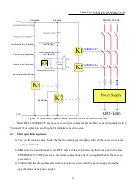
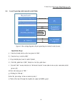
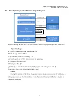
6.4. Laser Operating in External Control Programming Mode
Raycus Laser
XP3(Serial Interface)
XP5(Ethernet Interface)
1
2
XP2
17
18
19
20
(Security Interface)
AC INPUT
Figure 19Wiring diagram of external control laser emission in programming mode, in ON mode
Operations Steps
a) Turn the knob switch on the rear panel to“ON”
b)Turn the key switch to“ON”
c) Open the Raycus Laser Control System
d)Click the guide laser “ON” button to view the guide laser
e) Click the main power “ON”
f)Waiting for “Ready”
g)Set the pre-executed waveform number (the program number is greater than 0);
h)Start waveform at the rising edge of MOD signal.
NOTE:
The high-level time of MOD must be greater than the program running time. If MOD gives a
falling edge in advance, the Raycus Laser Control System will display that the laser program is
abnormally terminated.
PC
AC POWER
~380VAC
L1
L2
PE
Interlock1
Serial port line
Ethernet cable
MOD+
MOD -
Peripheral
Equipment
L3
Interlock2


