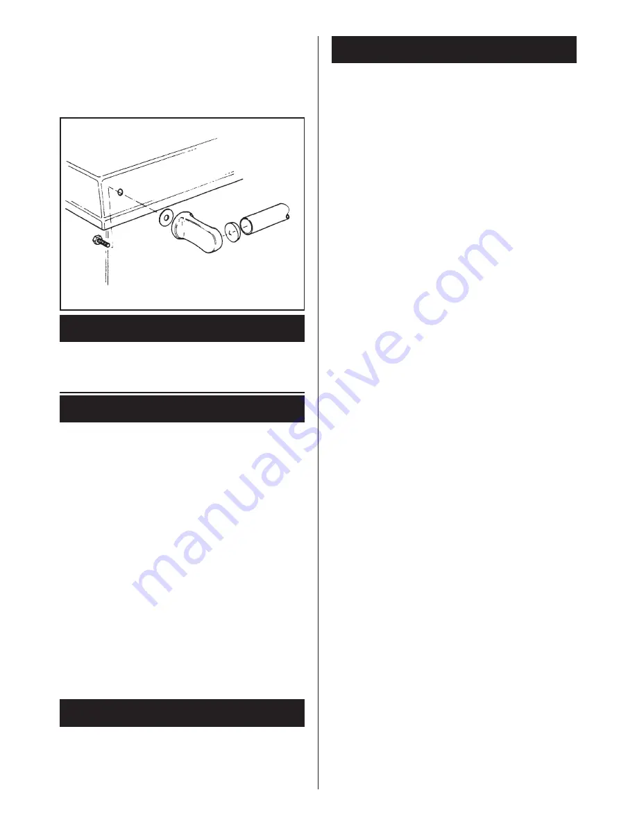
6. The handrail brackets are held on the front ends
of the cooker top-plate casting. Remove the travel
nuts and replace with handrail brackets ensuring
the fibre protecting washers are in position. Insert
the handrail with fitted endcaps into the brackets,
positioning them correctly, tighten the locating bolts.
(See Fig. 6A).
Connect the gas supply to the pre-formed 15mm O.D.
copper pipe from the integral union gas service cock on
the appliance.
A 230V ~ 50Hz electrical is required near to the appliance.
The appliance is supplied with a 0.75mm
2
(24 x 0.2mm) -
3 core PVC x 2 metres long 85ºC rated replaceable power
supply cable connected as described under Electrical
Supply.
A label attached to the end of the flexible cable gives
details of the cable core colour coding and their function
which should be adhered to. When connecting to a 3 pin
plug, observe the following recommendations:-
1. The wire which is coloured green-and-yellow must be
connected to the terminal in the plug which is marked
with the letter E or by the earth symbol or coloured
green or green and yellow.
2. The wire which is coloured blue must be connected to
the terminal which is marked with the letter N or
coloured black.
3. The wire which is coloured brown must be connected
to the terminal which is marked with the letter L or
coloured red.
The whole gas installation, must be inspected and tested
for soundness, and purged up to the appliance gas cock.
IMPORTANT: IF THE PILOT IS EXTINGUISHED FOR
ANY REASON, ALWAYS WAIT AT LEAST 3 MINUTES
BEFORE ATTEMPTING TO RELIGHT.
1.
Switch OFF the electricity supply at the wall
socket and ensure the optional programmer if
fitted is switched to the OFF position.
2.
Ensure that the thermostat knob
D
is at the O
position Fig. 7.
3.
Open the outer burner door
A.
4.
Turn ON the service cock
E
(below cooker burner
control valve) so that the screwdriver slot is in line
with pipework.
5.
Turn the control knob
B
to the ignition symbol and
depress it fully.
6.
Keeping control knob
B
depressed fully
simultaneously press Piezo Spark Generator
C
repeatedly until the pilot flame lights. This is
visible through the sight glass
F
(Fig. 7) (A few
seconds must be allowed for the gas to reach the
pilot burner).
7.
Continue to hold down Control Knob
B
for at least
15 seconds after the pilot flame has lit, then
release the knob slowly. The pilot flame will
remain if its presence has been detected by the
flame sensor unit.
8.
Check with leak detection fluid for gas soundness
at the joint of the pilot supply pipe with the control
valve.
9.
Check that the pilot flame is enveloping the pilot
thermocouple.
10.
With the thermostat knob
D
still at its setting O.
TURN the Control Knob
B
to the large main flame
symbol.
11.
Turn thermostat knob
D
to No. 9, turn ON the
electricity supply, and the programmer if fitted
requires setting to continuous.
12.
Check that the main burner flame has lit.
13.
Check that the pressure is correct.
14.
Check that the gas pressure is maintained and
unaffected when other gas appliances are used.
NOTE:- THIS APPLIANCE IS FITTED WITH A
COMBUSTION DISCHARGE SAFETY DEVICE WHICH
WILL SWITCH OFF THE MAIN BURNER IN ADVERSE
FLUE CONDITIONS. BEFORE TURNING ON MAIN
BURNER ENSURE THAT THE MANUAL RESET
BUTTON IS DEPRESSED. (FIG. 7).
15.
Check that there is no spillage of combustion
products from the appliance down-draught
diverter by carrying out a spillage test i.e. By
holding a smoke match so that the flame is
approximately 3mm up inside the lower edge of
the draught diverter. Spillage is indicated by the
smoke being displaced outward from the draught
diverter. Inspect flame pattern and appearance of
burner to establish that there is adequate air for
combustion.
16.
Turn the control knob
D
to O and remove the
pressure gauge from the burner test nipple, then
replace the sealing screw.
17.
Close outer burner door.
GAS INSTALLATION
ELECTRICAL CONNECTIONS
COMMISSIONING AND TESTING
LIGHTING THE BURNER -
See Fig. 7
5
Fig. 6A


