background image

Содержание CB-845

Страница 1: ...18 CHANNEL MOBILE CB TRANSCEIVER MODEL CB 845 INSTRUCTION HANDBOOK RAll JEFFERSOn CITIZEN BAND RADIO ...

Страница 2: ...ace age research and development The CB 845 is a completely solid state transistorized transceiver and contains no tubes to heat up draw a lot of current and burn out Space age inte grated circuits are used in the transceiver POSTAL AND TELECOMMUNICATIONS DEPARTMENT REQUIREMENT The station license must be applied for by submitting a properly completed station license application form Form RB 13 su...

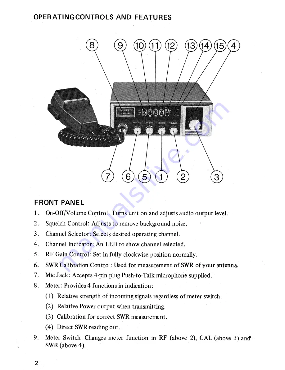
Страница 3: ... Control Set in fully clockwise position normally 6 SWR Calibration Control Used for measurement of SWR of your antenna 7 Mic Jack Accepts 4 pin plug Push to Talk microphone supplied 8 Meter Provides 4 functions in indication 1 Relative strength of incoming signals regardless of meter switch 2 Relative Power output when transmitting 3 Calibration for correct SWR measurement 4 Direct SWR reading ou...

Страница 4: ...n receiving an off frequen cy station 14 Transmit Indicator Lights up during transmission 15 Receive Indicator Lights up during reception REAR PANE L 1 Antenna connector Used for connection of antenna 2 DC Power Connector Used for connection of DC power source 3 External Speaker Jack Used for connection of external speaker 4 Public Address Speaker Jack Used for connection of PA speaker NOTE Insert...

Страница 5: ...informations ANTENNA CONNECTIONS A vertical whip antenna is best suited for mobile operation A non directional anten na should be used for best results in any case The base loaded whip antenna will normally provide effective communication or for greater range and more reliable operation a full quarter wave whip may be used Either of these antennas use the metal car body as a ground plane and the s...

Страница 6: ...WR MEASUREMENT PROCEDURE Your transceiver is equipped with the SWR measurement facilities for correct an tenna matching to transceiver Refer to followings 1 Connect a proper antenna system to the ANT connector 2 Turn power on 3 Place CB PA switch in CB position 4 Place the meter switch in CAL position 5 Depress the Push to Talk bar on the microphone 6 Adjust the Calibration control unitl the meter...

Страница 7: ...eceive mode only 3W at 8 ohm 13 8V DC On Off Volume control RF GAIN control Squelch control Meter switch CB PA switch NB ANL switch Tone switch Delta Tune RX and TX lamps S RF SWR meter Mic Jack Antenna Connector DC power jack PA speaker jack External speaker jack Frequency Control Channels Mode of Operation Receiving System Sensitivity at 10 dB S N Selectivity at 10 kHz Intermediate Frequency Fre...

Страница 8: ...EFFE RSON SCHEMATIC DIAGRAM ...

Страница 9: ...I C ER I VA LENT CI RCU ITS ofo vDD ...

Страница 10: ...IC2 IC3 1C2 V C O MIXER BUFFER IC3 OSC2 MIXER RF AMP TA7310P ...

Страница 11: ...IC 14 BALANCE MOD AN 612 37 ...

Отзывы: