


Fig. 24
IMPORTANT: Please, lubricate the
internal part of the seals before
fitting.
34
IMPORTANT:
These instructions must be read in
conjunction with the main installation and
servicing
instructions.
As with all fl ues the kits must be installed
taking due account of the current issue of BS
5440 parts 1 & 2 and timber frame housing
DM2 is referenced to the Institute of Gas
Engineers Document IGE/UP/7.
Also note that the requirements will vary
depending upon the kit being installed.
Guidance is provided but unless otherwise
stated, always comply with the
recommendations of the relevant codes of
practice.
5.13
INSTALLATION INSTRUCTIONS FOR TWIN FLUE PIPE (ECCENTRIC FLUE DUCT SYSTEM)
5.14 TWIN
FLUE
INSTRUCTIONS
This part of the installation manual covers the
installation
and
fi xing instructions of the twin
fl ue eccentric fl ue duct systems only.
When ordering twin fl ue it must be stated for
WH 80/90 (T) range.
Typical installation procedures are illustrated
by
drawings.
Remove the front panel of the case (sect.8.1).
Unscrew the screw (item 66 fi g. 17) on the
fl ue adapter.
Make sure that the fl ue manifold rubber seal
Make sure that the fl ue manifold rubber seal
is located into the fl ue manifold, and lubricate
is located into the fl ue manifold, and lubricate
the internal part of the seal before assembly.
the internal part of the seal before assembly.
Locate the header gasket on the twin fl ue
Locate the header gasket on the twin fl ue
header and push into the fl ue adaptor making
header and push into the fl ue adaptor making
sure that the inner plastic exhaust
sure that the inner plastic exhaust locates
fi rmly in the outlet spigot of the fl ue manifold,
and screw the securing screw that secure the
twin fl ue header on the boiler.
Locate the 2 x 80 mm O-rings in the twin
flue header and lubricate the internal part of
the seal before assembly to ensure easy
snug fi t.
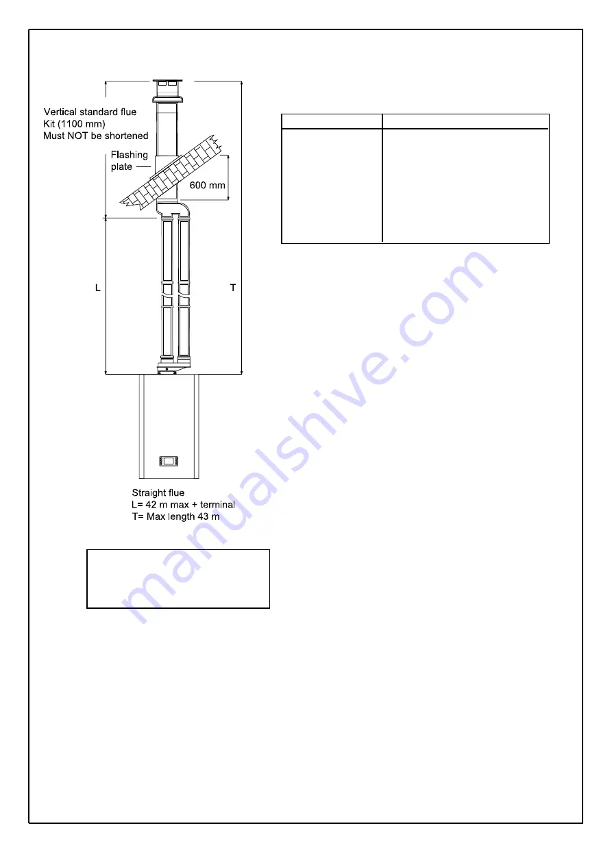
Figures show the versatility of this flueing
system. Measurements and bends must be
calculated correctly so as not to oversize
maximum flue lengths.
All located O-rings must be lubricated with a
silicone grease to ensure a snug fit.
NOTE: Exhaust flue must slope 1.5° down
towards the boiler 25 mm/m fall per metre of
flue length.
Spacing Clips
Spacing Clips are available on request should
they be required.
NOTE: for eccentric vertical flue a 125 mm
(5 in) diameter flashing plate will be required.
Part. No Description
SDO110050 Twin fl ue header F80/F80
PRO110200 Straight pipe L.1000 80
CUR110150 90° elbow bend 80
CUR110200 45° bend 80
GRI110050 Air inlet terminal 80
GRI110100 Exhaust terminal 80
TER060110 Vertical eccentric fl ue Terminal
TABLE 8
Содержание White Boiler WH 80
Страница 2: ...2 ...
Страница 21: ...21 4 10 FLUE TERMINAL POSITION ...
Страница 54: ...10 ELECTRICAL SYSTEM DIAGRAM 54 Fig 61 ...
Страница 55: ...55 11 SPARE PARTS Fig 62 ...
Страница 59: ......
Страница 62: ...61 ...
Страница 63: ...62 ...
Страница 65: ...64 FLOWCHART FOR CO LEVEL AND COMBUSTION RATIO CHECK ON COMMISSIONING A CONDENSING BOILER ...
Страница 66: ...65 12 1 ANALYSER CHECK LIST ...