background image

CHAPTER 5

40

Hawkeye® 2 Installation Manual for ET Apache Sprayers MY 2017+

Содержание RCM-Sprayer Hawkeye 2

Страница 1: ...Copyright 2021 Hawkeye 2 Installation Manual for ET Apache Sprayers MY 2017 016 0171 716 Rev A 6 2021 E37234 ...

Страница 2: ...aven Industries shall not be held responsible for any modifications or repairs made outside our facilities nor damages resulting from inadequate maintenance of this system As with all wireless and satellite signals several factors may affect the availability and accuracy of wireless and satellite navigation and correction services e g GPS GNSS SBAS etc Therefore Raven Industries cannot guarantee t...

Страница 3: ...ecommendations 27 Nozzle Control Valve 2 Installation 27 Boom Cable Routing and Connection 28 Best Practices and Recommendations 28 Boom Cable Routing and Connections Inner Middle and Outer Boom Cables 28 Chapter 5 RCM Sprayer Mounting and Connection 31 Mounting Plate Preparation 31 RCM Sprayer Installation 32 Install the RCM Sprayer 32 Mount the RCM Sprayer with Raven Autoboom XRT 33 Install the ...

Страница 4: ...Table of Contents ii Hawkeye 2 Installation Manual for ET Apache Sprayers MY 2017 ...

Страница 5: ...serve the following safety measures when operating the implement after installing this Raven system Do not operate this Raven system or any agricultural equipment while under the influence of alcohol or an illegal substance Be alert and aware of surroundings and remain in the operator seat at all times when operating this Raven system Do not operate the implement on any public road with this Raven...

Страница 6: ...ediate medical attention if symptoms of illness occur during or soon after use of agricultural chemicals or products After handling or applying agricultural chemicals Thoroughly wash hands and face after using agricultural chemicals and before eating drinking or using the restroom Thoroughly flush or rinse equipment used to mix transfer or apply chemicals with water after use or before servicing a...

Страница 7: ... especially in articulation and pivot points Clamp harnessing securely to force controlled movement of the harness Avoid abrasive surfaces and sharp edges such as sheared or flame cut corners fastener threads or cap screw heads hose clamp ends etc Do not connect affix or allow harnessing to come into contact with components with high vibration forces hot surfaces or components carrying hot fluids ...

Страница 8: ...CHAPTER 1 4 Hawkeye 2 Installation Manual for ET Apache Sprayers MY 2017 ...

Страница 9: ...orm which allows the system to work with most ISO Universal Terminals UTs and task controllers including the Viper 4 This manual is intended to provide installation instructions on the following equipment TABLE 1 Compatible Equipment Information Make and Model Nozzle Body Type Nozzle Spacing Boom Type Boom Width Kit Number Model Year 17 18 720 730 840 1020 1025 1030 1040 1220 1230 1240 TeeJet 15 S...

Страница 10: ... 135 100 117 2005 137 Pommier 100 117 2005 139 120 117 2005 130 132 117 2005 131 TeeJet 15 Standard 60 90 117 2005 143 90 117 2005 145 100 117 2005 147 Pommier 100 117 2005 149 120 117 2005 151 132 N A 20 Standard 60 90 117 2005 144 90 117 2005 146 100 117 2005 148 Pommier 100 117 2005 150 120 117 2005 141 132 117 2005 142 Hypro Arag 15 Standard 60 90 117 2005 156 90 117 2005 158 100 117 2005 160 ...

Страница 11: ... machine configuration tips REQUIRED COMPONENTS The following components must be installed with the Hawkeye 2 nozzle control system Updated software on field computers or control monitors PWM pump control valve Raven compatible flow meter Raven compatible pressure transducer 80 or finer mesh strainer NOTE Air induction style spray tips should not be used with the Hawkeye 2 nozzle control system A ...

Страница 12: ...ayers 115 2005 091 1 1 1 1 1 1 1 1 1 1 1 Cable Adapter ISO PCII to RCM 115 2005 095 1 1 1 1 1 1 1 1 1 1 1 Cable Mid 60 90 15 Spacing Apache STD Boom 115 2005 155 2 Cable Mid 60 90 15 Spacing Apache STD Boom 115 2005 148 2 Cable Mid 100 15 SPacing Apache STD Boom 115 2005 150 2 Cable Outer 60 90 15 Spacing Apache STD Boom 115 2005 149 2 2 2 Cable Mid 100 15 Spacing Apache Pommier Boom 115 2005 145 ...

Страница 13: ...he 120 20 Hawkeye 2 115 2005 089 2 Cable Mid Apache 132 20 Hawkeye 2 115 2005 093 2 Cable Outer Pommier 20 Spacing Apache Boom 115 2005 090 2 2 2 2 Kit Hawkeye 2 System Service Wilger 117 2005 052 1 1 1 1 1 1 1 1 1 1 1 Hex Bolt DIN931 M6 X 130MM A2 70 Stainless 304 311 4053 158 1 1 1 1 1 1 1 1 1 1 1 Hex Bolt DIN931 M6 X 140MM A2 70 Stainless 304 311 4053 159 2 2 2 2 2 2 2 2 2 2 2 Spacer 1 4 ID x 1...

Страница 14: ...n Black Size 116 219 2005 116 2 2 11 11 27 20 20 28 26 9 O Ring 38 Pack Viton Black Size 166 219 2005 116M 2 2 2 2 2 1 1 1 1 2 2 Cable Left Inner 90 100 15 Apache 115 2005 146 1 1 Cable Right Inner 90 100 15 Apache 115 2005 147 1 1 Cable Left Inner 90 100 15 Apache 115 2005 146 1 Cable Right Inner 90 100 15 Apache 115 2005 147 1 Cable Left Inner 100 15 Apache 115 2005 143 1 Cable Right Inner 100 1...

Страница 15: ...79 181 183 185 187 189 Sheet Warranty Help 016 0171 649 1 1 1 1 1 1 1 1 1 1 1 RCM Sprayer 063 0173 956 1 1 1 1 1 1 1 1 1 1 1 Cable NCV Power 28 Hawkeye 2 115 2005 008 1 1 1 1 1 1 1 1 1 1 1 Cable ECU Apache Sprayers 115 7303 143 1 1 1 1 1 1 1 1 1 1 1 Cable Adapter ISO PCII to RCM 115 2005 095 1 1 1 1 1 1 1 1 1 1 1 Cable Mid 60 90 15 Spacing Apache STD Boom 115 2005 155 2 Cable Mid 90 15 Apache STD ...

Страница 16: ...Boom 115 2005 103 2 2 Cable Mid 60 90 20 Spacing Apache STD Boom 115 2005 075 2 Cable Outer 60 90 20 Spacing Apache STD Boom 115 2005 076 2 Cable Mid 90 20 Spacing Apache STD Boom 115 2005 156 2 Cable Outer 90 20 Spacing Apache STD Boom 115 2005 157 2 Cable Mid 100 20 Spacing Apache STD Boom 115 2005 142 2 Cable Mid 100 20 Spacing Apache Pommier Boom 115 2005 134 2 Cable Mid Apache 120 20 Hawkeye ...

Страница 17: ...M6 X 140MM A2 70 Stainless 304 311 4053 159 2 2 2 2 2 2 2 2 2 2 2 Spacer 1 4 ID x 1 2 OD x 1 2 L Nylon Black 305 1001 009 1 1 1 1 1 1 1 1 1 1 1 Washer M6 Flat 304 SS 313 6000 011 6 6 6 6 6 6 6 6 6 6 6 Nut M6 Nylock 304 SS 312 6001 019 3 3 3 3 3 3 3 3 3 3 3 Hex Bolt DIN931 M6 X 70MM A2 70 Stainlesss 304 311 4053 146 1 1 1 1 1 1 1 1 1 1 1 Hex Bolt DIN931 M6 X 80MM A2 70 Stainlesss 304 311 4053 148 2...

Страница 18: ...1 1 Cable Right Inner 90 100 15 Apache 115 2005 147 1 1 1 Cable Left Inner 100 15 Apache 115 2005 143 1 Cable Right Inner 100 15 Apache 115 2005 144 1 Cable Left Inner 120 15 Apache 115 2005 100 1 Cable Right Inner 120 15 Apache 115 2005 101 1 Cable Inner 60 90 20 Apache 115 2005 074 2 2 Cable Inner 100 20 Apache 115 2005 141 2 Cable Inner 100 20 Apache 115 2005 133 2 Cable Apache 120 20 Hawkeye 2...

Страница 19: ... 1 1 1 1 1 1 1 1 1 1 Cable Adapter ISO PCII to RCM 115 2005 095 1 1 1 1 1 1 1 1 1 1 1 Cable Mid 60 90 15 Spacing Apache STD Boom 115 2005 155 2 Cable Mid 60 90 15 Spacing Apache STD Boom 115 2005 148 2 Cable Mid 100 15 Spacing Apache STD Boom 115 2005 150 2 Cable Outer 90 100 15 Spacing Apache STD Boom 115 2005 149 2 2 2 Cable Mid 100 15 Spacing Apache Pommier Boom 115 2005 145 2 Cable Mid 100 15 ...

Страница 20: ...2 Cable Mid Apache 120 20 Hawkeye 2 115 2005 089 2 Cable Mid Apache 132 20 Hawkeye 2 115 2005 093 2 Cable Outer Pommier 20 Spacing Apache Boom 115 2005 090 2 2 2 2 Kit Hawkeye 2 System Service TeeJet 117 2005 050 1 1 1 1 1 1 1 1 1 1 1 Hex Bolt DIN931 M6 X 130MM A2 70 Stainless 304 311 4053 158 1 1 1 1 1 1 1 1 1 1 1 Hex Bolt DIN931 M6 X 140MM A2 70 Stainless 304 311 4053 159 2 2 2 2 2 2 2 2 2 2 2 S...

Страница 21: ...5 116 2 2 11 11 27 20 20 28 26 9 O Ring Viton Purple Coated Size 115 219 2005 115 2 2 11 11 27 20 20 28 26 9 O Ring 38 Pack Viton Black Size 116 219 2005 116M 2 2 2 2 2 1 1 1 1 2 2 O Ring 38 Pack Viton Purple Coated Size 115 219 2005 115M 2 2 2 2 2 1 1 1 1 2 2 Cable Left Inner 90 100 15 Apache 115 2005 146 1 1 1 Cable Right Inner 90 100 15 Apache 115 2005 147 1 1 1 Cable Left Inner 100 15 Apache 1...

Страница 22: ...scription Part Number Qty 117 2005 156 158 160 162 164 157 159 161 163 154 155 Sheet Warranty Help 016 0171 649 1 1 1 1 1 1 1 1 1 1 1 RCM Sprayer 063 0173 956 1 1 1 1 1 1 1 1 1 1 1 Cable NCV Power Hawkeye 2 Apache Sprayers 115 2005 091 1 1 1 1 1 1 1 1 1 1 1 Cable Adapter ISO PCII to RCM 115 2005 095 1 1 1 1 1 1 1 1 1 1 1 Cable Mid 60 90 15 Spacing Apache STD Boom 115 2005 155 2 Cable Mid 60 90 15 ...

Страница 23: ...3 2 2 Cable Mid 60 90 20 Spacing Apache STD Boom 115 2005 075 2 Cable Outer 60 90 20 Spacing Apache STD Boom 115 2005 076 2 Cable Mid 90 20 Spacing Apache STD Boom 115 2005 156 2 Cable Outer 90 20 Spacing Apache STD Boom 115 2005 157 2 Cable Mid 100 20 Spacing Apache STD Boom 115 2005 142 2 Cable Mid 100 20 Spacing Apache Pommier Boom 115 2005 134 2 Cable Mid Apache 120 20 Hawkeye 2 115 2005 089 2...

Страница 24: ... L Nylon Black 305 1001 009 1 1 1 1 1 1 1 1 1 1 1 Washer M6 Flat 304 SS 313 6000 011 6 6 6 6 6 6 6 6 6 6 6 Nut M6 Nylock 304 SS 312 6001 019 3 3 3 3 3 3 3 3 3 3 3 Hex Bolt DIN931 M6 X 70MM A2 70 Stainlesss 304 311 4053 146 1 1 1 1 1 1 1 1 1 1 1 Hex Bolt DIN931 M6 X 80MM A2 70 Stainlesss 304 311 4053 148 2 2 2 2 2 2 2 2 2 2 2 Nozzle Control Valve Hawkeye 2 Arag Hypro 063 2005 002 73 73 81 81 97 54 ...

Страница 25: ...pache 115 2005 144 1 Cable Left Inner 120 15 Apache 115 2005 100 1 Cable Right Inner 120 15 Apache 115 2005 101 1 Cable Inner 60 90 20 Apache 115 2005 074 2 2 Cable Inner 100 20 Apache 115 2005 141 2 Cable Inner 100 20 Apache 115 2005 133 2 Cable Apache 120 20 Hawkeye 2 115 2005 088 2 Cable Inner Apache 132 20 Hawkeye 2 115 2005 092 2 Item Description Part Number Qty 117 2005 156 158 160 162 164 1...

Страница 26: ...1001 020 2 Not Pictured Fuse Mini Blade Type 15 Amp 510 1003 041 2 Picture Item Description Part Number Quantity Valve TeeJet Hawkeye 2 Nozzle Control 063 2005 002 1 Not Pictured Kit TeeJet Hawkeye 2 Valve Seal 117 2005 061 3 Not Pictured Cable Hawkeye 2 8 pin Ampseal Jumper 115 2005 070B 2 Not Pictured O Ring Size 115 Purple Viton Single 219 2005 115 1 Not Pictured Tool Hawkeye 2 Universal 321 00...

Страница 27: ...all service we provide We appreciate the opportunity to see ourselves as our customers see us and are eager to gather ideas on how we have been helping or how we can do better To serve you best please send an email with the following information to techwriting ravenind com Hawkeye 2 Installation Manual for ET Apache Sprayers MY 2017 016 0171 716 Rev A Any comments or feedback include chapter or pa...

Страница 28: ...CHAPTER 2 24 Hawkeye 2 Installation Manual for ET Apache Sprayers MY 2017 ...

Страница 29: ... strainer s with an 80 mesh strainer An 80 mesh or finer strainer is required for use with the Hawkeye 2 nozzle control system 7 If turret style nozzle bodies are installed on the implement rotate the turret to an open spray position if available If an open spray position is not available or for nozzle bodies without a turret remove the spray tips from the boom and set aside for later use 8 Enable...

Страница 30: ...CHAPTER 3 26 Hawkeye 2 Installation Manual for ET Apache Sprayers MY 2017 ...

Страница 31: ... excessive pressure drop across the nozzle NOZZLE CONTROL VALVE 2 INSTALLATION 1 Locate the Hawkeye 2 NCVs and the O rings provided with the kit NOTE If using TeeJet QJS straight nozzle bodies use the purple coated size 115 O rings If using TeeJet QJ turret nozzle bodies use the black size 116 O rings If Using Hypro Arag nozzle bodies use the purple size 115 O rings If Using Wilger nozzle bodies u...

Страница 32: ... cable routing near folding or break away points Route cables through existing cable retention devices as appropriate When securing the inner mid and outer boom cables on the implement begin at the outer boom tips Adjust the cable position to provide sufficient slack between valve tee branches while working toward the center of the implement Route the boom cables on the inside of the boom frame wh...

Страница 33: ...l range of motion without stretching the cable 4 Next repeat step 2 through 3 for the inner boom cable for the opposite side 5 Continue routing both mid and outer boom cables by starting each consecutive cable at the end of the previous cable and repeat step 2 through 4 until all cables have been routed NOTE The connector with the rotating locking collar will always go towards the center of the ma...

Страница 34: ...all boom cables are routed along the boom as desired begin connecting the boom cables to the Hawkeye 2 NCVs previously installed 9 Use provided cable ties to secure the boom cables to the boom components as needed to ensure they are secure NOTE Do not put strain on cables and connections while applying tie downs Do not leave any exposed cable loops that may get caught on crops or other debris whil...

Страница 35: ...e two bolts that secure the electrical box hood in place and lift the cover off of the electrical box to find the electrical mounting plate FIGURE 1 Electrical Panel Location 2 Locate the existing product controller ECU 3 Remove the bolts that secure the existing product controller ECU to the mounting plate 4 Remove the existing product controller ECU and disconnect the harness The product control...

Страница 36: ... RCM Sprayer Mounting Location and Orientation 3 Drill a hole for the M6 bolt to pass through at the marked location 4 Insert the 80MM M6 bolt through the RCM Sprayer top hole and the previously drilled hole 5 Loosely tighten a washer and lock nut to hold the RCM Sprayer in place but still allow it to rotate 6 Rotate the RCM Sprayer until the top is parallel to the top of the mounting plate 7 Mark...

Страница 37: ...hree M6 hex bolts securing the module to the bracket 3 In the Hawkeye 2 kit locate the M6 hex bolts one 130MM and two 140MM bolts black nylon spacer M6 washers and lock nuts 4 Insert the 130MM bolt through the top hole of the RCM Sprayer and equip with a nylon spacer 5 Insert the end of the 130MM bolt through the Autoboom module and through the existing mounting plate hole 6 Insert the two 140MM b...

Страница 38: ...eakout cable P N 115 2005 001 or 115 2005 091 provided in the kit 5 Connect the 23 pin connector black of the breakout cable to the remaining connector also black of the RCM Sprayer 6 Route the breakout cable down the center rack to the center boom section break as shown in Figure 5 Left Right Inner Cable Breakout following existing cabling and hose plumbing where possible 7 Connect the large roun...

Страница 39: ...nectors one of each gray black green brown grouped together and connect them to the matching connectors of the RCM Sprayer adapter cable P N 115 2005 095 previously installed 3 Connect the four pin ISObus plug from the cab to the four pin receptacle ISObus connector on the Hawkeye ECU harness P N 115 7303 143 FIGURE 6 ISOBus Connector 4 Connect the three pin plug to existing pressure transducer in...

Страница 40: ...he three pin jack to the flowmeter FIGURE 8 Flowmeter Connection 6 Connect the 12 pin receptacle on the Hawkeye ECU harness P N 115 7303 143 to the 12 boom section valve plug on the machine harness FIGURE 9 Boom Section Valve Connection Flowmeter Connection Boom Section Valve Connector ...

Страница 41: ...ye ECU harness P N 115 7303 143 to the tank fill receptacle on the machine cable harness if applicable FIGURE 10 ISO Tank Fill 8 Connect the four pin high current and switched power plug on the Hawkeye ECU harness P N 115 7303 143 to the receptacle on the machine cable harness FIGURE 11 High Current and Switched Power Connection ISO Tank Fill High Current and Switched Power ...

Страница 42: ...t to the corresponding connector of the power cable 3 Open the hood of the sprayer to access the power connections and route the power cable towards the sprayer battery compartment NOTE Follow the right frame rail towards the front of the machine 4 Locate the Ground Aux terminals on the power connection 5 Connect the ground cable from the power cable 115 2005 008 to the ground aux terminal 6 Conne...

Страница 43: ...ere the RCM Sprayer was installed FIGURE 13 ET Apache Center Rack Power Module 3 Connect the breakout cable black power connector to the matching connector on the power module box 4 Locate the ring terminal on the RCM Sprayer breakout cable 5 Locate the ground terminal on the back side of the mounting plate behind the power module FIGURE 14 ET Apache Center Rack Ground Connection 6 Remove one of t...

Страница 44: ...CHAPTER 5 40 Hawkeye 2 Installation Manual for ET Apache Sprayers MY 2017 ...

Страница 45: ...APPENDIX A System Diagram System Diagram 41 CHAPTERASYSTEM DIAGRAM SYSTEM DIAGRAM The system diagrams begin on the next page ...

Страница 46: ...1020 1025 1030 1220 1230 ITEM RAVEN P N ET P N DESCRIPTION 1 063 0173 956 RCM MAIN ECU 2 115 7303 143 ECU CABLE 3 115 2005 008 POWER CABLE 4 115 2005 095 PCII TO RCM ADAPTER CABLE 5 115 2005 001 ECU CABLE 6 408 4002 333 DUSTCAP ECO RELEASED DATE REV DRAWING NO 9 23 20 34661 A 054 2005 004 5 6 21 37347 B 054 2005 004 FLOW METER HAWKEYE CAN DIAGNOSTICS ISO CAN HC SW POWER ISO TANK FILL SECTION VALVE...

Страница 47: ...CU CABLE 3 115 2005 091 POWER CABLE 4 115 2005 095 PCII TO RCM ADAPTER CABLE TO OEM BULKHEAD CONNECTION BOOM VALVE POWER INJ POWER GND AB SENSE CAN HAWKEYE FENCE ROW FENCE ROW SECT 10 RIGHT FR SECT 7 SECT 9 PRESSURE SENSOR SECT 8 SECT 6 SECT 5 SECT 3 SECT 2 SECT 1 PWM SERVO FLOW METER ISO CAN LEFT FR CAN CH2 SECT 4 TO SYSTEM HAWKEYE POWER TO LEFT BOOM TO RIGHT BOOM TO SYSTEM GROUND SHEET 2 OF 3 EC...

Страница 48: ...03 QTY 73 063 2005 001 063 2005 002 063 2005 003 QTY 54 063 2005 001 063 2005 002 063 2005 003 QTY 81 063 2005 001 063 2005 002 063 2005 003 QTY 62 063 2005 001 063 2005 002 063 2005 003 QTY 81 063 2005 001 063 2005 002 063 2005 003 QTY 60 063 2005 001 063 2005 002 063 2005 003 QTY 97 063 2005 001 063 2005 002 063 2005 003 QTY 72 N A 063 2005 001 063 2005 002 063 2005 003 QTY 80 N A KITS MY 17 18 ...

Страница 49: ... Nozzle Control Valves NCV perform the following steps to all 6 pin NCV connectors and 19 pin circular connectors between the boom cables and ECU cable connections to ensure high quality connections 1 Verify the NCV connectors and the accompanying boom cable connectors are free of moisture contamination or oxidation Oxidation will appear as a dry white coating on the contacts If any connectors sho...

Страница 50: ... debris 5 Remove residue of the deoxidizing agent from the connection 6 Dry out the connection with dry compressed air such as Dust Off Electronics Duster P N 222 4001 007 or equivalent air duster suitable for electronic components NOTE If using compressed air from a large volume air compressor be sure the lines are free of moisture FIGURE 3 Electronics Duster Used on NCV CAUTION Damage to the con...

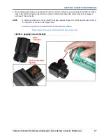
Страница 51: ... Be sure the corrosion inhibitor has coated the NCV2 contacts and recessed portions of the connector NOTE To determine whether corrosion inhibitor has been applied inspect for a thick liquid in the bottom of the connector as shown in the image below CorrosionX may also be purchased from the manufacturer website https www corrosionx com products corrosionx heavy duty FIGURE 4 Applying Corrosion Inh...

Страница 52: ...APPENDIX B 48 Hawkeye 2 Installation Manual for AGCO RoGator C Series RG900 RG1100 RG1300 ...

Страница 53: ...er s responsibility The Return Materials Authorization RMA number must appear on the box and all documentation including proof of purchase must be included inside the box to be sent to Raven Industries WHAT WILL RAVEN INDUSTRIES DO Upon confirmation of the warranty claim Raven Industries will at our discretion repair or replace the defective product and pay for the standard return freight regardle...

Страница 54: ... claim and send it to Raven Industries for final approval The freight cost to Raven Industries will be the customer s responsibility The Return Materials Authorization RMA number must appear on the box and all documentation including proof of purchase must be included inside the box to be sent to Raven Industries In addition the words Extended Warranty must appear on the box and all documentation ...

Отзывы: