Raven AutoBoom XRT Series Скачать руководство пользователя страница 49

APPENDIX

A

45

APPENDIX A

KITS LISTS

AUTOBOOM XRT KITS

The following kits are included in this appendix: 

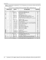
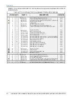
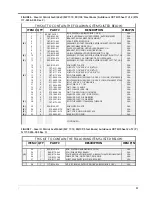
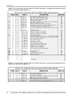
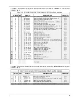
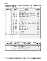
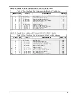
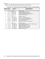
TABLE 1. AutoBoom XRT Kits

Kit Description

Kit Number-

Kit, Hydraulic, AutoBoom, Case IH, 3320/4420

117-0134-075

Kit, AutoBoom XRT, Case IH Patriot, 3XX0/44X0, MY 17-18, 120’ Steel Boom

117-0236-001

Kit, AutoBoom XRT, Case IH Patriot, 3XX0/44X0, MY 17-18, 120’ Steel Boom No Hydraulics

117-0236-002

Kit, AutoBoom XRT, Case IH Trident, 5550, MY 17-18, 120’ Steel Boom 

117-0236-003

Kit, AutoBoom XRT, Case IH Trident, 5550, MY 17-18, 120’ Steel Boom No Hydraulics

117-0236-004

Kit, AutoBoom XRT, Case IH Patriot, 3XX0/44X0, MY 17-18, 90’ - 100’ Steel Boom 

117-0236-005

Kit, AutoBoom XRT, Case IH Patriot, 3XX0/44X0, MY 17-18, 90’ - 100’ Steel Boom No 

Hydraulic

117-0236-006

Kit, AutoBoom XRT, Case IH Trident, 5550, MY 17-18, 90’ - 100’ Steel Boom

117-0236-007

Kit, AutoBoom XRT, Case IH Trident, 5550, MY 17-18, 90’ - 100’ Steel Boom No Hydraulics

117-0236-008

Kit, AutoBoom XRT, Boom, Case IH 120’

117-0236-021

Kit, AutoBoom XRT, Damper, Case IH, Patriot

117-0236-023

Kit, AutoBoom XRT, Boom, Case IH, 90’/100’

117-0236-024

Содержание AutoBoom XRT Series

Страница 1: ...Copyright 2018 2019 AutoBoom XRT Installation Manual for Case IH Patriot 3XX0 44X0 and Trident 5550 MY 2017 19 016 0236 001 Rev C 7 2019 E33444...

Страница 2: ...ven Industries shall not be held responsible for any modifications or repairs made outside our facilities nor damages resulting from inadequate maintenance of this system As with all wireless and sate...

Страница 3: ...Already Installed 12 Mount the AutoBoom XRT Valve 15 Install the Pressure and Tank Hoses 16 Install the Left and Right Cylinder Hoses 18 Install the Left and Right Return Hoses 19 XRT Hydraulic Schem...

Страница 4: ...Table of Contents ii AutoBoom XRT Installation Manual for Case IH Patriot 3XX0 44X0 and Trident 5550 MY 2017 19 Connect the Harness to the Sensors 43 Appendix A Kits Lists 45 AutoBoom XRT Kits 45...

Страница 5: ...ert and aware of surroundings Do not operate any agricultural equipment while under the influence of alcohol or an illegal substance Remain in the operator s position or a safe working distance away f...

Страница 6: ...ith machine components which develop temperatures higher than the temperature rating of hose components Hoses should be protected or shielded if it needs to route near hot temperatures beyond hose com...

Страница 7: ...s of machined surfaces Fastener threads or cap screw heads Ends of adjustable hose clamps Wire exiting conduit without protection either ends or side of conduit Hose and tube fittings Routing should n...

Страница 8: ...operators might step or use as a grab bar Damage when passing through metal structures IMPORTANT Avoid directly spraying electrical components and connections with high pressure water High pressure wa...

Страница 9: ...TRODUCTION The AutoBoom XRT system is designed to provide automated boom height adjustment for agricultural equipment This manual applies to the following machines MAKE Case IH MODEL Patriot 3XX0 44X0...

Страница 10: ...s boom hydraulic functions i e tilt fold center rack tongue extension or other hydraulic valve functions three times to ensure the machine s hydraulic valve is using fresh oil and debris is flushed f...

Страница 11: ...n page 21 REM node installation instructions in Mount the AutoBoom XRT Valve on page 15 ABM node installation instructions in Autoboom ABM Node Installation on page 35 Tilt sensor installation instruc...

Страница 12: ...the future of our product documentation and the overall service we provide We appreciate the opportunity to see ourselves as our customers see us and are eager to gather ideas on how we have been help...

Страница 13: ...019 Case IH Patriot 3XX0 44X0 120 No 117 0236 001 117 0236 021 117 0236 023 Optional Yes 117 0236 002 117 0236 021 117 0236 023 Optional Case IH Trident 5550 120 No 117 0236 003 117 0236 021 117 0236...

Страница 14: ...CHAPTER 2 10 AutoBoom XRT Installation Manual for Case IH Patriot 3XX0 44X0 and Trident 5550 MY 2017 19...

Страница 15: ...r routine service ensure precautions are taken to prevent any foreign material from being introduced into the machine s hydraulic system Objects or materials that are able to bypass the machine s hydr...

Страница 16: ...ssary to remove the existing AutoBoom node and mounting plate as well as remove the orifice fittings in the AutoBoom valve The AutoBoom valve will be reused for the AutoBoom XRT installation 1 Locate...

Страница 17: ...FIGURE 3 Port Plugs Removed from the AutoBoom Valve 4 Remove the orifice fittings from Ports 3A and 3B FIGURE 4 Orifice Fitting Removed from the AutoBoom Valve NOTE Tip the AutoBoom valve on its side...

Страница 18: ...Trident 5550 MY 2017 19 5 Use the Allen wrench to reinstall the port plugs on Ports 3A and 3B of the AutoBoom valve FIGURE 5 Port Plug Reinstalled on the AutoBoom Valve 6 Reinstall the coils on the s...

Страница 19: ...ing Location NOTE Mount the AutoBoom valve so that Port P is facing up and LC and RC Ports are facing the center of the machine FIGURE 8 AutoBoom XRT Valve Mounted on the Sprayer 2 Mount the REM node...

Страница 20: ...Hydraulics are under pressure Care should always be taken with a system that has been pressurized When disconnecting or purging hydraulic hoses be aware that the hydraulic fluid within the machine s s...

Страница 21: ...0 end of the installed hydraulic hose to Port P on the AutoBoom valve FIGURE 11 Pressure and Tank Hoses Installed 9 Disconnect the machine s tank hose from the machine s hydraulic valve 10 Install a 8...

Страница 22: ...raulic block 5 Connect the machine s right tilt hose to the opposite end of the tee fitting installed in the right tilt port of the machine s hydraulic valve 6 Connect the 90 end of the supplied hydra...

Страница 23: ...cylinder return hose to the opposite end of the tee fitting installed in the right return port 5 Connect the 90 end of the supplied hydraulic hose P N 214 1000 494 to the 90 end of the installed tee f...

Страница 24: ...CHAPTER 3 20 AutoBoom XRT Installation Manual for Case IH Patriot 3XX0 44X0 and Trident 5550 MY 2017 19 AUTOBOOM XRT HYDRAULIC SCHEMATIC FIGURE 14 AutoBoom XRT Hydraulic Diagram P N 054 0236 001...

Страница 25: ...ght side of the center rack just below where the existing cable is routed NOTE Weld studs on the center rack may need to be removed for proper damper installation and operation FIGURE 15 Welding Stud...

Страница 26: ...loosely install the other damper mounting bracket to the back of the center frame vertical tube with the two holes facing towards the outside 5 Using the provided 5 8 clevis pins install the damper s...

Страница 27: ...a belt tighten the ratchet strap until the damper is the desired length 9 With the cylinder end of the damper at the top use the provided 5 8 clevis pins to install the top damper in the top holes on...

Страница 28: ...CHAPTER 3 24 AutoBoom XRT Installation Manual for Case IH Patriot 3XX0 44X0 and Trident 5550 MY 2017 19...

Страница 29: ...e approximate mounting locations for various boom widths The information on this table is for reference only If there is interference or other issues with these mounting locations mount the sensors as...

Страница 30: ...n locking nuts per sensor P N 312 4000 164 NOTE Install two of the sensors in one orientation and three in the other orientation on the bracket so when installed the sensor connection is facing toward...

Страница 31: ...3 Inner Boom Sensor Installed 120 Boom Shown NOTE For other boom configurations where the sensor assembly doesn t fit between the rails mount the sensor behind the boom 5 Mount the center sensor asse...

Страница 32: ...e the open position between the center rack and center frame to mount the rotary sensor FIGURE 5 Center Rack Rotary Sensor Assembly for 120 Booms 2 Assemble the items in above figure to the rotary sen...

Страница 33: ...ioned between the center rack and the center frame The sensor mounts on the right side of the center The connector on the sensor will point down the left side of the machine 5 Install the rotary senso...

Страница 34: ...ition 90 100 BOOM 1 Locate the open position between the center rack and center frame to mount the rotary sensor FIGURE 9 Center Rack Rotary Sensor Assembly for 90 100 Booms 2 Assemble the items in ab...

Страница 35: ...bolts to loosely install the rotary sensor assembly labeled Center Rack 90 100 FT to the lower horizontal tube positioned between the center rack and the center frame The sensor mounts on the right si...

Страница 36: ...when installed the tilt bracket sensor arm should be on the back of the boom FIGURE 12 Tilt Sensor Bracket Installed Right Boom Shown 2 Loosely install the tilt sensor assembly to the angled boom stru...

Страница 37: ...ck nut 7 Tighten all hardware installation hardware 8 Repeat step 1 through step 7 to install the left boom sensor PROXIMITY SENSOR NOTE The following steps are not required for machines with 120 boom...

Страница 38: ...CHAPTER 4 34 AutoBoom XRT Installation Manual for Case IH Patriot 3XX0 44X0 and Trident 5550 MY 2017 19 FIGURE 15 Proximity Sensor Mounting Proximity Sensor Spacer Existing Bracket...

Страница 39: ...6 1 2 or 3 8 x 7 1 2 bolts secure the AutoBoom node mounting bracket P N 107 0235 009 to the machines frame in front of the battery box FIGURE 1 Installed AutoBoom XRT Node 3 Using the provided 1 4 2...

Страница 40: ...acket P N 107 0235 033 using 1 4 2 nylon lock nuts The connectors of the ABM should face away from the gusset 2 Use the provided 7 16 x 1 75 bolts washers and nylon lock nuts to mount the ABM bracket...

Страница 41: ...016 0236 001 Rev C 37 WIRING INSTALLATION ELECTRICAL DIAGRAMS FIGURE 4 AutoBoom XRT System Diagram for 120 Booms P N 054 0236 001...

Страница 42: ...CHAPTER 5 38 AutoBoom XRT Installation Manual for Case IH Patriot 3XX0 44X0 and Trident 5550 MY 2017 19 FIGURE 5 AutoBoom XRT System Diagram for 90 100 Booms P N 054 0236 005 Rev C...

Страница 43: ...nect the RIGHT CYLINDER POSITION plug to the 4 pin receptacle on the Superseal Position Sensor cable P N 115 0235 069 8 Route and connect the other end of the cable P N 115 0235 069 to the previously...

Страница 44: ...the XRT Cable 20 Reconnect the machine s harness or CAN terminator to the other end of the CAN tee 21 Connect the machine s AUX POWER connector to the LOGIC POWER connector on the AutoBoom harness NOT...

Страница 45: ...115 0235 113 to the mating connector on the bottom of the REM node 2 Plug black 23 pin plug on the XRT cable to the mating connector on the bottom of the REM node 3 Plug black 35 pin plug on the XRT c...

Страница 46: ...way up AutoFold will require recalibration once these sensors are adjusted 10 Connect the CENTER RACK ANGULAR POSITION plug to the 4 pin receptacle on the Superseal Position Sensor cable P N 115 010...

Страница 47: ...13A on the AutoBoom XRT valve CONNECT THE HARNESS TO THE SENSORS 1 Starting at the outside sensor on the right boom and working towards the center connect the secondary boom cable to the outside heig...

Страница 48: ...CHAPTER 5 44 AutoBoom XRT Installation Manual for Case IH Patriot 3XX0 44X0 and Trident 5550 MY 2017 19...

Страница 49: ...17 18 120 Steel Boom 117 0236 003 Kit AutoBoom XRT Case IH Trident 5550 MY 17 18 120 Steel Boom No Hydraulics 117 0236 004 Kit AutoBoom XRT Case IH Patriot 3XX0 44X0 MY 17 18 90 100 Steel Boom 117 02...

Страница 50: ...LBOW 90 SWIVEL 6 ORFS M F 2 333 0012 069 4 FTG SWIVEL RUN TEE 6 ORFS M M F 3 333 0012 084 2 FTG ADAPTER STR 6 ORFS M TO 6 SAE O RING M 4 333 0012 165 2 FTG ELBOW 90 6 ORFS M TO 8 SAE O RING M 5 333 00...

Страница 51: ...872 220 81 2 7 6 7 72 217 1 7 2 2 1 7 06 67 2 2 6 33 1 2 2 9 9 5 8 26 17 5 872 220 57 5 7 1 0 12 02817 675 3 527 5 6 1625 5 029 5 7 0 12 1 3 7 02817 1 9 9 1 5 0 326 7 21 6 1625 7 7 53 3 75 27 683 56 3...

Страница 52: ...1 1 1 1 1 1 1 1 1 6 5 2 1 3 7 6 5 7 1 552 6 5 7 1 552 1 1 1 683 56 326 7 21 6 1625 72 3 1 66 0 527 5 6 1625 872 220 57 17 5 5 19 23 3 67 8 2 7 7 8 2 7 7 52 7 5 0 2 7 0 1 21 67 1 66 6 2 7 0 1 21 67 1...

Страница 53: ...625 72 3 1 66 0 527 5 6 1625 872 220 57 17 5 5 19 23 3 67 2 7 8 2 7 7 8 2 7 7 52 7 5 0 2 7 0 1 21 67 1 66 6 2 7 0 1 21 67 1 66 67 2 7 5 187 1 21 2 187 1 2 187 1 21 2 1 66 2 6 33 1 2 2 9 9 5 8 26 17 5...

Страница 54: ...7 0 5 1 52 1 2 6 33 1 2 2 6 7 55 17 3 8 62 86 5 0 5 9 1 8 5 9 1 872 220 57 0 7 872 220 81 2 7 6 7 72 217 1 7 2 2 1 7 06 67 2 2 6 33 1 2 2 683 56 326 7 21 6 1625 72 3 1 66 0 527 5 6 1625 872 220 57 17...

Страница 55: ...0 7 5 6 19 23 3 67 187 0 187 2 1 21 16 57 0 3 7 02817 1 9 9 1 5 0 5 7 52 1 220 683 56 326 7 21 6 1625 72 3 1 66 0 527 5 6 1625 872 220 57 5 7 7 7 7 5 8 872 220 6 66 0 527 5 6 1625 872 220 57 7 7 7 6...

Страница 56: ...5 6 1625 872 220 57 17 5 5 5 7 0 12 1 217 18 52 7 5 00 0 7 5 6 19 23 3 67 187 0 187 2 1 21 16 57 0 5 1 52 1 3 7 02817 1 9 9 1 5 0 66 0 527 5 6 1625 872 220 57 5 7 7 7 683 56 326 7 21 6 1625 72 3 1 66...

Страница 57: ...7 5 6 19 23 3 67 187 0 187 2 1 21 16 57 0 3 7 02817 1 9 9 1 5 0 66 0 527 5 6 1625 872 220 57 5 7 7 7 683 56 326 7 21 6 1625 72 3 1 66 0 527 5 6 1625 872 220 57 7 7 7 6 7 5 8 872 220 6 19 23 3 67 187 1...

Страница 58: ...5 872 220 57 5 7 7 7 5 7 0 12 75 17 217 18 52 7 5 00 0 7 5 6 19 23 3 67 187 0 187 2 1 21 16 57 0 5 1 52 1 3 7 02817 1 9 9 1 5 0 66 0 527 5 6 1625 872 220 57 7 7 7 6 683 56 326 7 21 6 1625 72 3 1 19 23...

Страница 59: ...1 2 7 3 36 3 1 187 1 21 2 1 66 187 1 2 2 6 33 1 35 0 5 220 57 6 21 5 220 57 6 1625 220 7 5 5 80 5 5 7 5 5 6 1625 19 23 3 67 8 2 7 7 7 6 7 72 217 1 7 2 2 1 7 06 67 2 7 1 1 1 1 1 1 1 1 1 1 1 7 0 47 2 0...

Страница 60: ...N 117 0236 024 Rev C 7 1 1 1 1 1 1 1 1 1 1 1 1 1 1 1 1 1 1 1 7 0 47 2 6 5 37 21 3 57 2 6 33 1 2 7 3 36 3 1 187 1 21 2 1 66 187 1 2 8 2 7 7 5 19 23 3 67 02 7 21 6 1625 352 0 7 3 6 63 5 352 0 7 6 7 2 7...

Страница 61: ...c Safety 2 Introduction Hydraulic Fittings 7 Kit Contents 9 Hydraulic Kit 9 Optional Inner Ultrasonic Sensor Installation Kit 9 Preparing or Installation 6 Point of Reference 6 Recommendations 6 Tools...

Страница 62: ...Index 42 AutoBoom XRT Installation Manual for Case IH Patriot 3XX0 44X0 and Trident 5550 MY 2017 19...

Страница 63: ...r s responsibility The Return Materials Authorization RMA number must appear on the box and all documentation including proof of purchase must be included inside the box to be sent to Raven Industries...

Страница 64: ...claim and send it to Raven Industries for final approval The freight cost to Raven Industries will be the customer s responsibility The Return Materials Authorization RMA number must appear on the box...

Отзывы: