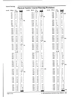
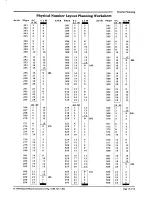
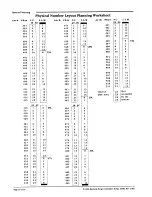
background image

System Planning

Introduction to System Planning

Summary:

FUNCTIONS:

REMOTE
LOCATIONS:

QUANTITY:

TCIV LINES:

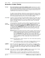
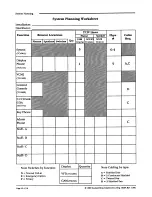
This section describes the System Planning Worksheet, which 

provides space for creating a

clear, concise, and comprehensive listing of system requirements. Using it will help ensure a
correct and sucessful cost estimate and provide a useful tool for use when ordering, installing,
and programming the system. Read the following while reviewing the example to get a full
understanding of the worksheet and how to complete it.

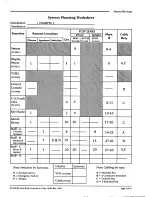
The System Planning Worksheet is divided into six major planning areas: Function, Remote
Locations, Quantity (Qty.), TCIV Lines, Physical Numbers (Phys. #), and Cabling. An ad-
ditional block at the bottom provides space for planning additional Display requirements.
The following paragraphs explain each area and how it should be completed.

Functions are chosen according to the operational features desired by the customer. They es-
tablish the requirements for Remote Location  and TCIV Line hardware. Space is provided so
that four different Staff functions (A, B, C, D) can be defined on one sheet. This should be
enough in most cases. Definitions and special notes should be written on the worksheet
where ever appropriate.

These are the stations where people use Phones, Speakers, and Switches to perform a func-
tion associated with a single line. In the example, a 

1 in 

any 

Phone 

or Speaker block indi-

cates one unit is required at each remote location. 

Switches 

are designated by type 

E

(Emergency), N (Normal), and 

P (Privacy). 

A horizontal line indicates the item is not needed

in the example system. 

Shadowed areas 

indicates the option doesn’t apply in any system.

(i.e., Speakers and Switches cannot be on the same line as a Call Control Console or Key

Phone and TC4160  VCM’s  and TC4171 COA’s require TCIV lines but they are not used by
people at remote locations).

Phones: The 

example system uses several types of phones to support a variety of functions. It

includes a Display Phone, three Key Phones, an Administrative Phone, and twenty
Multi-Link Staff Phones. (Note: Multi-link phones can be identied by looking at
their LLM

 and Physical 

Number requirements. Only multi-link staff phones

require one LLM line and one physical number each.) Another Staff Function (Staff-
D) could be specified for single- link staff phones and only one physical number

would be required for all of them. However, each of them would use a Phone

SCC25 line.

Speaker: The example system requires 43 speakers. One at each remote location performing

a Staff function (A, B, or C).

Switch: The example system requires 15 Normal and 15 Emergency switches: one of each

type of switch at each remote location performing the 

Staff - B 

function.

(QTY.): This is the total number of each type of Function required. In the example system
there is: 1 Display Phone, 8 

Staff - A 

stations (each requiring a speaker), 15 

Staff - B 

stations

(each requiring a speaker with a normal and an emergency call-in switch), and 20 

Staff - C

stations (each requiring a phone and speaker). There are also 6 Central Office Trunks and 3
Key Phones.

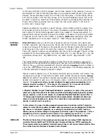
This is where you determine the 

Phone 

and 

Speaker 

hardware required to meet the needs

determined by the number and types of Functions and Remote Locations.

Phone 

equipment is required to support telephone and hands-free intercom paths. The

amount of hardware required is determined by the number of TC4 150 Line-Link Module

Page 

2

 of

 16 

 1989 

Rauland-Borg Corporation (Orig.  10/88;  Rev. l/89)

Содержание Telecenter IV

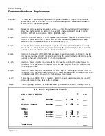
Страница 1: ...and worksheets are provided to enable a clear concise and comprehensive listing of require ments for use in ordering system installation and programming Because the Telecenter IV may or may not be connected to the public telephone network the manual is divided into two parts RI 1581 Internal System Planning and KI 1582 Intercon nect Planning Only the information necessary to plan a system which do...

Страница 2: ...es the option doesn t apply in any system i e Speakers and Switches cannot be on the same line as a Call Control Console or Key Phone and TC4160 VCM s and TC4171 COA s require TCIV lines but they are not used by people at remote locations Phones The example system uses several types of phones to support a variety of functions It includes a Display Phone three Key Phones an Administrative Phone and...

Страница 3: ......

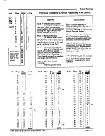
Страница 4: ...ng physical numbers is one of the most complex and important parts of system design The following paragraphs de scribe the mechanics of assigning physical numbers Physical numbers relate to pins on the SC25 and SCC25 SC and TC4150 LLM boards They are assigned in groups of consecutive numbers which provide the required overlap between LLM and SC boards This overlap is required when speakers and pho...

Страница 5: ......

Страница 6: ......

Страница 7: ...reas of the System Planning Worksheet LCD Display phone These are recommended for use as Attendant Phones and for system programming A display phone may be coupled with a speaker and any combina tion of call in switches VFD Vacuum Fluorescent Displays One VFD is required at each location staffed by Attendant stations which do not have display phones Note LCD Drivers 1 and 2 can each drive up to 3 ...

Страница 8: ...er the annunci ated or monitored lines If both types of lines are required to flash but at differ ent rates a pulse generator may be required for each Design and obtain materials for a custom display panel allowing mounting space for the TM432 modules For each type of line annunciated and monitored provide a 34 conductor flat cable long enough to supply lamp driver signals to each GAM plus enough ...

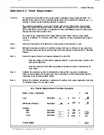
Страница 9: ...uired A Phone SC line is required for each Single Link Staff Phone Refer to your definition of Staff Functions for the quantity of Single Link phones required and enter that number on the appropriate function line under Phone SCC25 A Speaker SC line is required for each Speaker Refer to the Quantity column of your System Planning Worksheet and enter the number of Speaker SC25 lines required for ea...

Страница 10: ...t to the next whole number if a fraction is obtained Determine the number of TC4165 VCM expansion chassis required by subtracting one 1 from the total number of VCMs required and dividing the remainder by four 4 Increase the quotient to the next whole number if a fraction is obtained Determine Power Amplifier requirements for All Page by summing the output power re quirements of all speakers in th...

Страница 11: ...ep 2 Estimate the maximum number of multi link phones that may be off hook at any given time 32 off hook phones will use all sixteen lines Note this number in the formula for Off Hook Phones Step 3 Review the power rating of each speaker assigned to each VCM Note the number of VCMs with all speakers rated at no more than than 2 watts in the formula for 2W VCMs Note the number of VCMs with any spea...

Страница 12: ......

Страница 13: ......

Страница 14: ......

Страница 15: ......

Страница 16: ......

Отзывы: