background image

35

   - Replacement of the plug or the supply cord shall always be carried out by the manufacturer of 

the tool or his service organisation,


- Keep water clear off the electrical parts of the tool and away from persons in the working area.

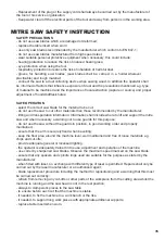
MITRE SAW SAFETY INSTRUCTION


SAFETY PRECAUTIONS


- do not use saw blades which are damaged or deformed;


- replace the table insert when worn;


- use only saw blades recommended by the manufacturer which conform to EN 847-1;


- do not use saw blades manufactured from high speed steel;


- wear suitable personal protective equipment when necessary, this could include:


- hearing protection to reduce the risk of induced hearing loss; 


- eye protection when using the tool.


- respiratory protection to reduce the risk of inhalation of harmful dust.


- gloves  for  handling  saw  blades  (saw  blades shall  be  carried  in  a  holder wherever 

practicable) and rough material;


- connect the saw to a dust collecting device when sawing wood. In addition the operator shall 

be informed of factors that influence exposure of dust and the precautions mentioned e.g. type 

of material to be machined and the importance of local extraction (capture or source) and proper 

adjustment of hoods/baffles/chutes;


SAFE OPERATION


- select the correct saw blade for the material to be cut;


- do not use the saw to cut other materials than those recommended by the manufacturer;


- lifting and transportation information: Information shall include where to lift and support the mitre 

saw and when necessary a warning not to use guards for this purpose;


- do not use the saw without the guards in position, in good working order and properly 

maintained;


- ensure that the arm is securely fixed when bevelling;


- keep the floor area around the machine level, well maintained and free of loose materials e.g. 

chips and cut-offs;  


- provide adequate general or localised lighting;


- the operator is adequately trained in the use, adjustment and operation of the machine;


- use correctly sharpened saw blades. Observe the maximum speed marked on the saw blade;


- ensure that any spacers and spindle rings used are suitable for the purpose as stated by the 

manufacturer;


- when fitted with laser, no exchange with different type of laser is permitted. Repairs shall only be 

carried out by the laser manufacturer or an authorised agent;


- blade replacement procedure including the method for repositioning and a warning that this must 

be carried out correctly;


- refrain from removing any cut-offs or other parts of the workpiece from the cutting area whilst the 

machine is running and the saw head is not in the rest position;

   - always to clamp work pieces to the saw table


- to ensure before each cut that the machine is stable,


- if needed, to fix the machine to a work bench or the like,


- if needed, to support long work pieces with appropriate additional supports;


- replace table insert when worn.

Содержание IR1200NM

Страница 1: ...Serra de esquadria ...

Страница 2: ...Instrucciones en Español Instruções no Portugués Instructions in English ...

Страница 3: ...ificio para montaje 11 Perilla de seguridad de la pinza 12 Pinza 13 Bolsa para el polvo 14 Protección de disco superior 15 Empuñadura para transporte 16 Puerto de extracción de serrín Ver Fig A 17 Pie de soporte Ver Fig B2 18 Interruptor Ver Fig F 19 Palanca de bloqueo de bisel Ver Fig G1 20 Escala de bisel Ver Fig M2 21 Bloqueo del husillo Ver Fig N2 No todos los accesorios ilustrados o descritos...

Страница 4: ...N 61029 ADVERTENCIA El valor de emisión de vibraciones durante el uso real de la herramienta eléctrica puede diferir del valor declarado en función de los modos en que se utilice la herramienta de acuerdo a los siguientes ejemplos y otras variaciones de uso Cómo se utiliza la herramienta y los materiales que se cortan o perforan Si la herramienta se encuentra en buen estado y se ha mantenido adecu...

Страница 5: ...e seguir siempre las precauciones de seguridad básicas para evitar riesgos de incendio descargas eléctricas y lesiones personales además de las que se mencionan posteriormente Lea todas las instrucciones antes de utilizar este producto y guárdelas Mantenimiento Desenchufe la herramienta antes de realizar cualquier ajuste reparación o mantenimiento CÓMO UTILIZAR LA HERRAMIENTA DE FORMA SEGURA 1 Man...

Страница 6: ...Siga las instrucciones para lubricar y sustituir los accesorios Inspeccione los cables periódicamente y en caso de que estén dañados pida a un técnico de servicio especializado que los repare Observe los cables de alargo periódicamente y sustitúyalos si están dañados Mantenga los tiradores secos limpios y sin grasa 15 Desconecte las herramientas Cuando no las utilice antes de realizar el mantenimi...

Страница 7: ...ra reducir el riesgo de pérdida auditiva inducida Protecciones oculares durante el uso de la herramienta Protección respiratoria para reducir el riesgo de inhalación de polvo nocivo Guantes para manipular los discos deben ir en un protector siempre que sea posible y el material rugoso Conecte la sierra al dispositivo de recolección de polvo cuando vaya a serrar madera Además el operador deberá ser...

Страница 8: ...5 a 45 así como ángulos de bisel verticales de 0 a 45 MONTAJE ADVERTENCIA Para evitar el encendido accidental y posibles daños graves monte SIEMPRE todas las piezas de la sierra ANTES de conectarla a la toma de corriente La sierra NUNCA debe estar conectada a una toma de corriente cuando monte piezas realice ajustes instale o retire discos o cuando no la esté utilizando 1 PUERTO DE EXTRACCIÓN DE S...

Страница 9: ... que los tornillos de ajuste de la pinza están ajustados 4 ORIFICIOS DE MONTAJE VER FIG D Antes de usarla la sierra se puede fijar a una superficie firme y nivelada con 4 pernos de montaje no incluidos La sierra incluye 4 orificios en la base para poder fijarla a un banco o a otra superficie de soporte Para montarla siga estos pasos 1 Localice y marque la zona exacta donde montará la sierra 2 Perf...

Страница 10: ...e desea cortar en la tabla rotativa y asegúrese de que queda fijado con firmeza para que no se mueva durante el corte 3 Asegúrese de que la perilla de bloqueo de la mesa rotativa 7 y la palanca de bloqueo del bisel 19 están bien ajustadas antes del corte 4 Encienda la sierra y espere a que el disco adquiera la velocidad máxima 5 Manteniendo pulsado el interruptor presione con el pulgar la palanca ...

Страница 11: ...mpuesto es un corte que requiere la configuración de inglete y la de biselado Se puede realizar de la misma forma que el corte clásico o como un corte cruzado en función de la anchura de la pieza Se pueden lograr cortes en inglete compuestos configurando los ángulos en inglete y biselado simultáneamente Siga el procedimiento para realizar los cortes en ingletes y biselados para lograr los ángulos ...

Страница 12: ...ecesita ajustarse afloje los tornillos c para alinear la guía con la escuadra Vuelva a ajustar los tornillos c para alinear la guía VER FIG K1 K2 De forma similar compruebe que el ángulo del disco de cara a la mesa rotativa es de 90o Si fuera necesario ajuste el ángulo de inclinación del cabezal en la posición de 90º afloje la perilla de bloqueo del bisel 19 y ajuste el tornillo del bisel a 0o d p...

Страница 13: ...be periódicamente los cepillos de carbono Si se desgastan hasta tener un grosor inferior a 4 mm debe sustituirlos por un nuevo set de cepillos no incluidos Deben cambiarse de dos en dos Con un destornillador plano gire el capuchón en dirección contraria a las agujas del reloj hasta que quede liberado el cepillo de carbono Sustitúyalo y asegúrese de que se acoplan correctamente y quedan bien fijado...

Страница 14: ...a Describa con precisión el posible motivo de la reclamación y si nuestra prestación de garantía incluye su defecto el aparato será reparado o reemplazado por uno nuevo de igual o mayor valor según nuestro criterio Esta garantía no es válida por defectos causados como resultado de 1 Mal uso abuso o negligencia 2 Uso profesional 3 Intento de reparación por personal no autorizado 4 Daños causados po...

Страница 15: ...15 ...

Страница 16: ...10G 46 2 47 BMS210G 47 1 48 BMS210G 48 8 49 BMS210G 49 1 50 BMS210G 50 1 51 BMS210G 51 1 52 BMS210G 52 5 53 BMS210G 53 1 54 BMS210G 54 1 55 BMS210G 55 1 56 BMS210G 56 1 57 BMS210G 57 1 58 BMS210G 58 1 59 BMS210G 59 1 60 BMS210G 60 1 61 BMS210G 61 1 63 BMS210G 63 1 64 BMS210G 64 4 65 BMS210G 65 2 66 BMS210G 66 1 67 BMS210G 67 2 68 BMS210G 68 1 Núm Referencia Cant 69 BMS210G 69 1 70 BMS210G 70 1 71 ...

Страница 17: ...arafuso do grampo de aperto rápido 12 Grampo de aperto rápido 13 Saco para o pó 14 Capa de proteção superior 15 Pega para transporte 16 Orifício de extração dos detritos ver Fig A 17 Posição do suporte Ver Fig B2 18 Botão de Ligar Desligar Ver Fig F 19 Alavanca de bloqueio do bisel Ver Fig G1 20 Escala de biselamento Ver Fig M2 21 Bloqueio do eixo Ver Fig N2 Nem todos os acessórios ilustrados ou d...

Страница 18: ...es soma triaxial de vetores estão em conformidade com a norma EN AVISO O valor da emissão de vibrações durante a utilização da ferramenta elétrica pode diferir do valor apresentado dependendo da forma como se usa a ferramenta de acordo com os exemplos seguintes e de outras variações na utilização da ferramenta O modo de usar a ferramenta e os materiais que estão a ser cortados ou perfurados A ferr...

Страница 19: ... realizar Veja a embalagem do acessório para mais detalhes Os funcionários da loja poderão ajudá lo e aconselhá lo INSTRUÇÕES TRADUZIDAS PARA PORTUGUÊS AVISO Sempre que usar ferramentas elétricas deve respeitar as instruções de segurança de forma a minimizar o risco de incêndio choque elétrico e lesão pessoal incluindo o seguinte Leias estas instruções na totalidade antes de tentar colocar este pr...

Страница 20: ...brificação e à substituição de acessórios Verifique os fios da ferramenta regularmente e se estiverem danificados leve a um reparador oficial para que a arranje Verifique as extensões regularmente e se estiverem danificadas substitua as Mantenha as mãos secas limpas e isentas de óleo ou lubrificante 15 Tirar a ficha da tomada Quando não estiver a utilizar as ferramentas antes de realizar reparaçõe...

Страница 21: ...e incluir se proteção para os ouvidos para reduzir o risco de perda auditiva induzida proteção para os olhos sempre que utilizar a ferramenta proteção respiratória para reduzir o risco de inalar poeiras nocivas luvas para manusear os discos de serra deve usar um suporte para transportar os discos de serra sempre que possível e material resistente quando estiver a serrar madeira coloque um recipien...

Страница 22: ... a 45 assim como cortes angulares de bisel na vertical de 0 a 45 MONTAGEM AVISO Para prevenir o funcionamento acidental que pode provocar lesões pessoais graves monte SEMPRE as peças todas na serra ANTES de ligar a ficha à tomada A serra NUNCA deve estar ligada à corrente elétrica sempre que estiver a montar as peças a fazer ajustes a colocar ou remover discos ou quando não estiver a utilizá la 1 ...

Страница 23: ... Certifique se de que os parafusos de fixação do grampo estão apertados 4 ORIFÍCIOS DE MONTAGEM VER FIG D Antes de usar a serra pode fixá la numa superfície firme e nivelada com os 4 parafusos de montagem não incluídos A base da serra conta com quatro orifícios de modo a que seja possível fixá la numa bancada ou noutras superfícies de apoio Para montar a serra proceda da seguinte forma 1 Localize ...

Страница 24: ...em no disco nem no prato 2 Posicione o material que irá cortar sobre o prato giratório certifique se de que está firmemente preso de modo a que não se mova durante o corte 3 Garanta que o manípulo de bloqueio do prato giratório 7 e a alavanca de bloqueio do bisel 19 estão apertados antes de começar a cortar 4 Prima o botão de ligar desligar e aguarde que a velocidade do disco aumente 5 Ainda a pre...

Страница 25: ...ontal apenas no lado esquerdo Desaperte a alavanca de bloqueio do bisel 19 e incline a cabeça da serra para a esquerda até alcançar o ângulo desejado na escala de biselamento Volte a prender a alavanca de bloqueio do bisel e corte 6 CORTE COMPOSTO VER FIG J Um corte composto é um corte que requer uma configuração tanto em esquadria como em bisel Pode ser executado como corte longitudinal ou como c...

Страница 26: ...ção a 0o do prato giratório coloque o a 0o e aperte o manípulo de bloqueio do prato giratório Comprove se o ângulo entre a guia e o disco é de 90 utilizando um esquadro b não incluído como demonstrado na Fig K1 Se for necessário ajustar o ângulo desaparafuse os parafusos de bloqueio c da guia e alinhe o carril indicador pelo esquadro Volte a apertar os parafusos de bloqueio c da guia VER FIG K1 K2...

Страница 27: ...isco 3 SUBSTITUIR AS ESCOVAS DE CARBONO Verifique regularmente as escovas de carbono Se as escovas de carbono apresentarem um desgaste de 4 mm substitua as por um novo conjunto não incluído Deve substituir se o par Com uma chave de fendas apropriada rode a tampa em sentido contrário ao dos ponteiros do relógio até conseguir soltar as escovas de carbono substitua as escovas e certifique se que estã...

Страница 28: ...e a política de garantia cobrir a sua queixa repararemos ou substituiremos por um produto exatamente igual ao seu ou outro de categoria superior de acordo com o nosso critério Esta garantia é nula se os defeitos forem causados por 1 Má utilização abuso ou negligência 2 Utilização profissional 3 Reparações anteriores realizadas em centros de assistência técnica não autorizados 4 Danos causados por ...

Страница 29: ...29 ...

Страница 30: ...10G 46 2 47 BMS210G 47 1 48 BMS210G 48 8 49 BMS210G 49 1 50 BMS210G 50 1 51 BMS210G 51 1 52 BMS210G 52 5 53 BMS210G 53 1 54 BMS210G 54 1 55 BMS210G 55 1 56 BMS210G 56 1 57 BMS210G 57 1 58 BMS210G 58 1 59 BMS210G 59 1 60 BMS210G 60 1 61 BMS210G 61 1 63 BMS210G 63 1 64 BMS210G 64 4 65 BMS210G 65 2 66 BMS210G 66 1 67 BMS210G 67 2 68 BMS210G 68 1 Posição N º N º da peça Qtd 69 BMS210G 69 1 70 BMS210G ...

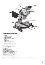
Страница 31: ...ounting hole 11 Work clamp securing knob 12 Work clamp 13 Dust bag 14 Upper blade guard 15 Transportation handle 16 Dust extraction port See Fig A 17 Support stand See Fig B2 18 Trigger switch See Fig F 19 Bevel lock lever See Fig G1 20 Bevel scale See Fig M2 21 Spindle lock See Fig N2 Not all the accessories illustrated or described are included in standard delivery 1 2 3 4 5 6 7 8 9 10 11 12 13 ...

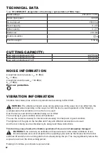
Страница 32: ...on the ways in which the tool is used dependant on the following examples and other variations on how the tool is used How the tool is used and the materials being cut or drilled The tool being in good condition and well maintained The use the correct accessory for the tool and ensuring it is sharp and in good condition The tightness of the grip on the handles and if any anti vibration accessories...

Страница 33: ...pting to operate this product and save these instructions Maintenance and Servicing Remove the plug before carrying out any adjustment servicing or maintenance SAFE OPERATION 1 Keep work area clear Cluttered areas and benches invite injuries 2 Consider work area environment Do not expose tools to rain Do not use tools in damp or wet locations Keep work area well lit Do not use tools in the presenc...

Страница 34: ...e tool before turning it on 17 Avoid unintentional starting Ensure switch is in off position when plugging in 18 Use outdoor extension leads When the tool is used outdoors use only extension cords intended for outdoor use and so marked 19 Stay alert Watch what you are doing use common sense and do not operate the tool when you are tired 20 Check damaged parts Before further use of tool it should b...

Страница 35: ...ose recommended by the manufacturer lifting and transportation information Information shall include where to lift and support the mitre saw and when necessary a warning not to use guards for this purpose do not use the saw without the guards in position in good working order and properly maintained ensure that the arm is securely fixed when bevelling keep the floor area around the machine level w...

Страница 36: ...ORT SEE FIG A To reduce build up of saw dust and maintain top efficiency of cutting the saw dust collection can be achieved by clipping a dust bag on the dust extraction port 16 A dust bag is provided for use on your miter saw To install it simply fit the dust bag over the extraction port on the upper blade guard To empty the dust bag remove it from the dust exhaust port open the dust bag by unzip...

Страница 37: ...el surface with the 4 mounting bolts not supplied Four holes are provided in the base of the saw to enable it to be fixed to a bench or other supporting surface To mount the saw proceed as follows 1 Locate and mark where the saw is to be mounted 2 Drill 4 holes through the surface 3 Place the sliding miter saw on the surface aligning holes in base with holes drilled in the surface Install bolts wa...

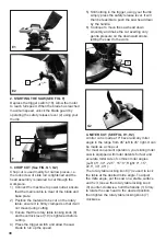
Страница 38: ...ed 5 Still holding in the trigger using your thumb simply press the safety release lever It will then be feasible to push the saw head down by the handle 6 Continue to move the saw head down smoothly and make the cut exerting only gentle pressure on the downward stroke letting the saw do the work 4 MITER CUT SEE FIG H1 H2 A miter cut is made at 0 bevel and any miter angle in the range from 45 left...

Страница 39: ...djustments settings or maintenance have been done make sure that all keys and wrenches have been removed and that all screws bolts and other fittings are securely tightened There are no user serviceable parts in your power tool Never use water or chemical cleaners to clean your power tool Wipe clean with a dry cloth Always store your power tool in a dry place Keep the motor ventilation slots clean...

Страница 40: ...el lock 19 and adjust the 0 bevel adjustment screw d to bring the saw blade into alignment with the square Loosen the head screw d holding the pointer of the bevel scale 20 and adjust the position of the pointer so that it accurately indicates zero on the scale Retighten the screw Retighten the bevel lock 19 and the 0 bevel adjustment screw d SEE FIG L1 L2 2 CHANGING THE SAW BLADE SEE FIG N1 N5 Di...

Страница 41: ...aw head is locked in the lower position 2 The rotary table locking knob the bevel lock lever and the slide rod securing knob must all be securely tightened 3 Use the transportation handle to lift the saw Do not lift the saw by the switch handle ENVIRONMENTAL PROTECTION Waste electrical products should not be disposed of with household waste Please recycle where facilities exist Check with your Loc...

Страница 42: ...roduct Description Mitre Saw Type IR1200NM MS designation of machinery representative of Mitre Saw Function Cutting wood and analog materials Complies with the following Directives 2006 42 EC 2014 30 EU 2011 65 EU Standards conform to EN 61029 1 EN 61029 2 9 EN 55014 1 EN 55014 2 EN 61000 3 2 EN 61000 3 3 Date 11 17 2016 Company name Ehlis S A CEO Alejandro Ehlis ...

Страница 43: ...43 ...

Страница 44: ...G 45 2 46 BMS210G 46 2 47 BMS210G 47 1 48 BMS210G 48 8 49 BMS210G 49 1 50 BMS210G 50 1 51 BMS210G 51 1 52 BMS210G 52 5 53 BMS210G 53 1 54 BMS210G 54 1 55 BMS210G 55 1 56 BMS210G 56 1 57 BMS210G 57 1 58 BMS210G 58 1 59 BMS210G 59 1 60 BMS210G 60 1 61 BMS210G 61 1 63 BMS210G 63 1 64 BMS210G 64 4 65 BMS210G 65 2 66 BMS210G 66 1 67 BMS210G 67 2 68 BMS210G 68 1 69 BMS210G 69 1 70 BMS210G 70 1 71 BMS210...

Страница 45: ......

Страница 46: ......

Страница 47: ......

Страница 48: ......

Отзывы: