background image

WIRING

C. Mounting  controls:

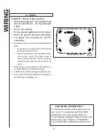
A.  Push Button Switch: (see fig 11)

Mount Push Button Switch in an accessible
location.

Make certain wires can be routed to Push
Button Switch.

Wire terminals must have clearance when
installed.

1. Drill 5/8" (16mm) hole.
2. Attach wires to Push Button Switch terminals (see

wiring section).

3. Install Push Button Switch through back of

mounting surface.

4. Install waterproof nut on Push Button Switch.
5. Secure in place with inner nut.

B.  ME  Toilet Control:

1. Cut out a hole per Fig. 12, mark

mounting  holes using wall plate as guide.

2. Route wire to the toilet and control.

3. Secure control with gasket using two

screws.

C.  Smart Flush Control:

1. Cut out a hole per Fig. 13, mark mounting

holes using wall plate as guide.

2. Route wire to the toilet and control.

3. Secure control  using mounting

screws

Install the Warning Label (L322) where it can be
easily seen.

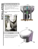
Mounting Remote Pump:

1. Locate  remote pump between thru hull fitting and

toilet bowl.

2. Locate in an area away from berth to keep noise

level down.

3. Use Inline Strainer (optional) to avoid clogs.
4. Secure remote pump to the floor  using four bolts

through the pump base.

11

Fig.11

1/4” min clearance from terminals

CUT OUT

Multifunctional Manual Switch

Fig. 12

Содержание Elegance

Страница 1: ...gonlytheabilityto flushwithnoindependantcontrolofwateror Marine Elegance Elegance Elegance Elegance Elegance THE FOLLOWING ARE CAUTIONARY STATEMENTS THAT MUST BE READ AND FOLLOWED DURING BOTH INSTALLA...

Страница 2: ...pinstalled between the intake pump and the toilet bowl Doubleclampallbelowwaterlineconnections Recommended Visual Inspection 3 3 3 3 3 For leaks at toilet and hose connections 3 3 3 3 3 Hoseclamps 3 3...

Страница 3: ...to evacuatethebowl Dischargepumprunsas longasthisbuttonisheld 2 Water Only Press Water Only switch to addwaterinthebowl Inletwatersolenoid pumprunsaslongasbuttonispressedwith asevensecondslimit After...

Страница 4: ...retention fill Time After placing the unit in program mode Step 1 above push the WATER ONLY button the number of times required for the Water Valve Inlet Pump time one push ZERO sec s two 1 sec three...

Страница 5: ...et 1m long 1 25 mm or 1 1 2 38 mm I D discharge hose approximately3feet 1m long Two buckets Nontoxicantifreezeapproximately1quart 1liter Steps 1 Close the intake and discharge seacocks 2 Turnoffpowert...

Страница 6: ...2 p o r d e g a t l o v 3 r o f 4 5 0 1 n o d e s a b e r a s e z i s r o t c u d n o c d e d n e m m o c e R o n o i t a l u s n i d e t a r C s g n i t a r n o i t a l u s n i r e h t o r o f s d r...

Страница 7: ...dist 7 8 Hence a maximum of 7 high loop can be installed 6 4 2 0 20 40 60 80 100 0 120 140 160 180 Horizontal distance Feet Marine Elegance discharge Maximum recommended 1 PVC hose length Parts inclu...

Страница 8: ...ket assembly to deck using 14 self threading bolts and flat washers Note place bolts as close to mark linesA B and C as possible 5 Drill holes for discharge 1 5 8 41 mm inlet hose 7 8 22mm andwires 3...

Страница 9: ...lampallbelow waterlineconnections IMPORTANT Fittings and 90 bends should be kept to a minimum In Line Strainer may be installed on Sea Water Models per Installation Instructions This will prevent clog...

Страница 10: ...ed 1 Slidefittingclipstoopenposition 2 Select inlet port to be used 3 Installappropriatefittingsintoinletandoutletports NOTE The 90 fitting can be rotated 360 4 Installtheplugfittingintounusedinletpor...

Страница 11: ...g holesusingwallplateasguide 2 Route wire to the toilet and control 3 Securecontrolwithgasketusingtwo screws C Smart Flush Control 1 Cut out a hole per Fig 13 mark mounting holesusingwallplateasguide...

Страница 12: ...power source for remote pump to remote pump and back Same wire gauge mustbeusedforbothlowerbaseandremote pump 2 Select proper wire and fuse circuit breaker size fromSpecificationsonInstallationpage 3...

Страница 13: ...noid valve Discharge pump Fig 14 Wiring for Push Button Switch Fresh water model To EST Discharge pump Black RED Blue Blue Black RED Fuse Pump Relay RED Push Button Push Button BATTERY 13 Fig 14A Wiri...

Страница 14: ...L PANEL FUSE BREAKER orange black red black red black panel tankfullswitch ESTinput BATT FLUSH CONTROL PANEL FUSE BREAKER Relay PUMP remote Fig 15 WIRINGFOR SMART SWITCH FRESHWATER MODEL Fig 16 WIRING...

Страница 15: ...Breaker red orange black blue black red RED Relay Fig 18 WIRING FOR ME TOILET CONTROL WITH REMOTE PUMP Fig 17 WIRINGFOR ME TOILET CONTROL FRESHWATER MODEL Solenoid Valve Discharge Pump Discharge Pump...

Страница 16: ...necthosesandwireplugs see Fig 19 Caution Do not pull on the discharge hose to avoid kinking 8 Installmountingbushings bolts SeeFig 20 9 Tightenboltsbeingcarefultonotovertighten Do notexceed30inchlb wh...

Страница 17: ...chargeline 4A Pressurebuildupatseacocks 5A LeakingBowlThroatadapter 5B Leakatshaftseal 5C Leak from bowl spud SOLUTION 1A Besuredischargeseacockisopen Clearline remove clog 1B Replumbtoeliminatebendsa...

Страница 18: ...F195 Front mounting washer 1 F196 Front mounting snap cap 1 M23A Lockwasher 166000 Remote pump complete 12v 166100 Remote pump complete 24V 1660 Motor raw water pump 161115 Impeller 161123 Macerator...

Страница 19: ...5 162225 162135 162100W 162420 162200W 190601 Recommended EXPLODED PARTS F193 freshwater strainer Recommended Seawater strainer 19 FIG 21 221100 F186VT 221210 221110 221150 221300 161123 161115 31 102...

Страница 20: ...psupplied byothersintheprocessofinstallationofthisproduct defectscausedbyinstallationofthisproduct otherthaninaccordancewiththemanufacturer srecommendedinstallationinstructionsorstandard industryproce...

Отзывы: