1
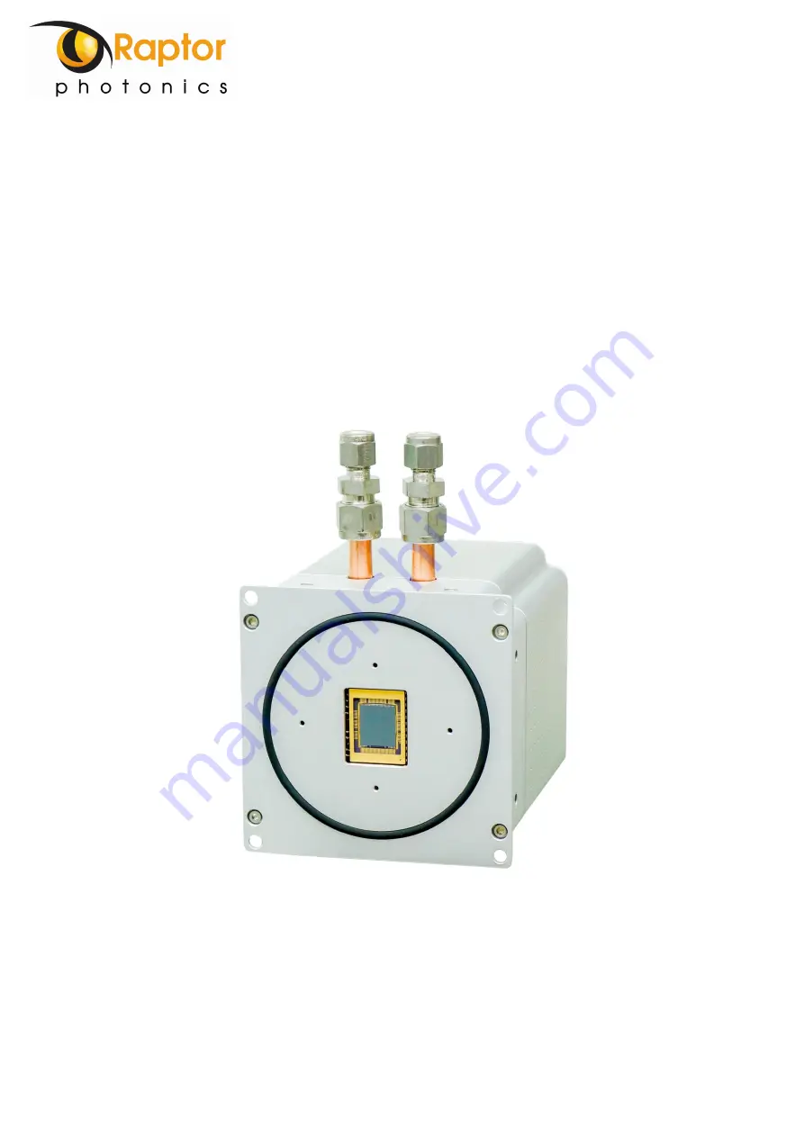
Eagle XV
Models:
EA4240XV-BN-CL, EA4240XV-BNDD-CL, EA4710XV-BN-CL,
EA4710XV-BNDD-CL
USER MANUAL
Страница 1: ...1 Eagle XV Models EA4240XV BN CL EA4240XV BNDD CL EA4710XV BN CL EA4710XV BNDD CL USER MANUAL...
Страница 2: ...um Pressure 11 5 CAMERA CHILLER SETUP 12 5 1 Liquid Cooling 12 5 1 1 Liquid Cooling Connection to the Camera Head 12 5 2 2 Connecting the Camera and Chiller 13 5 1 3 Recommended Coolants for the Chill...
Страница 3: ...3 Trigger Control 23 9 3 1 Live ITR Integrate then Read 23 9 3 2 Live FFR Fixed Frame Rate 23 9 3 3 Ext Triggered External Trigger 23 9 3 4 Btn Triggered Snapshot Trigger 23 9 3 5 Pixel Readout Clock...
Страница 4: ...pe Detailed information is provided on each of the cameras control parameters as well as stating important precautions to take when operating the camera Each camera control is discussed and explained...
Страница 5: ...and liquid cooling in a vacuum environment This level of cooling gives an ultra low dark current reading of 0 0005e p s in the standard sensor format allowing for longer integration times The Camera L...
Страница 6: ...Mechanical Model Power supply weight 1 5kg Units shown in inches mm Figure 2 Solid Works Model Basic 2D mechanical dimensions of the camera PDF of the 2D mechanical model available from our website w...
Страница 7: ...7 Figure 3 Solid Works Model basic dimensions of the power supply module Power supply weight 0 5kg Units shown in inches mm...
Страница 8: ...ng for O D pipe 3 TTL Trigger output 50ohm SMA Exposure 4 TTL Trigger output 50ohm SMA Readout 5 Camera link connector Base MDR 3M P N 10226 6212PC 6 Label recess Model Number Serial Number 7 TTL Trig...
Страница 9: ...g by screwing the module to a metal surface 3 5 Trigger IN External synchronisation with the start of integration signal may be achieved using the Trigger IN connector Input impedance 510 200pF input...
Страница 10: ...tamination from the local environment see Figure 4 It is recommended to keep the temporary plate and O ring for storage of the camera when not in use or for transportation Regarding storage temperatur...
Страница 11: ...ensor if this background signal is affecting your data acquisition it may be necessary to switch off the pressure gauge once you are satisfied that steady state conditions have been achieved Never coo...
Страница 12: ...rwise damage to the camera will occur 5 1 1 Liquid Cooling Connection to the Camera Head The camera electronics drive a ThermoElectric Cooler TEC to cool the CCD The hotside of the TEC MUST be cooled...
Страница 13: ...Recommended Coolants for the Chiller The recommended coolants are Option 1 Distilled Water Option 2 95 distilled water and 5 isopropyl alcohol mixture prevents bio growth Option 3 80 distilled water...
Страница 14: ...e of the feedthrough must protrude into the vacuum chamber The power cable with grey insulation is intended for in vacuum connection Always ensure the cable polarity is correct before attempting to pl...
Страница 15: ...ended cut out is 65mm x 26mm as shown in Figure 8 The bulkhead flange must be secured using 4 off screws at the corners also indicated in Figure 8 Figure 8 Dimensions and cut out for Camera Link Feedt...
Страница 16: ...e and format options 6 4 Liquid Feedthrough Optional Item Coolant connections to the Swagelok fittings on the camera head can be made using OD pipe and a feedthrough flange such as that shown in Figur...
Страница 17: ...ile which can be used to control the camera on National Instruments imaging tools such as NI MAX The file may also be useful if attempting to create your own LabView VI 7 4 Custom Software Interfacing...
Страница 18: ...rom another company the specification requirements of this frame grabber must meet those supplied by the PIXCI EB1 model If using a laptop EPIX offers base Camera Link frame grabbers for a laptop syst...
Страница 19: ...ing Open w Default Video Setup will open the control panel with all control parameters set to the default states Open w Last used Video Setup will open the control panel with all parameters set at the...
Страница 20: ...l have three moving dots that flash This indicates that you are obtaining video data from the camera The imaging statistics displayed directly underneath the imaging window will also inform you if you...
Страница 21: ...p gain will be enabled offering the lowest noise If you are imaging with a higher intensity signal high preamp gain can be disabled The exposure time and frame rate controls are shown under every tab...
Страница 22: ...closed Permanently open Open for the duration of a valid exposure time Additional delay registers may also be programmed to allow a shutter to be fully open before and fully closed after the exposure...
Страница 23: ...osure Rate becomes active when this mode is selected giving the user control to program the frame rate 9 3 3 Ext Triggered External Trigger If this mode is enabled then the camera will use an external...
Страница 24: ...mage may be read from the camera instead of CCD data The test image will consist of a fixed ramp pattern that will start with a value of 0 on the first pixel read from the camera and increment by one...
Страница 25: ...gle XV 47 10 model Also ROI width and ROI height must be 0 Binning In addition to standard 1 1 output various levels of pixel binning may be programmed up to 64 64 Pixel binning is performed on the CC...
Страница 26: ...ing must be used when using the TEC This is needed to dissipate heat away from the hot side of the TEC Do not enable the TEC if liquid cooling is not being used otherwise damage to the camera will occ...
Страница 27: ...the camera was built ADC DAC Calibration Values These are calibration values that are used to set the TEC set point and read back the sensor and PCB temperatures They are not needed for the user as t...
Страница 28: ...ixinc com manuals pixci_eb1 index htm This section will discuss in detail a few features on XCAP that Raptor thinks would be of immediate use when using the camera 10 1 Recording Images on XCAP Captur...
Страница 29: ...settings file If the camera is set to a desired state outside of the default state clicking Save 1 will save all the current parameter states that have been set This can be done a further two times Th...
Страница 30: ...ication will have to be re enabled each time In the contrast modification box that can be seen from Figure 24 select Stretch Contrast Histogram Percentile Endpoints and click preview The contrast modi...
Страница 31: ...31 CORPORATE HEADQUARTERS Raptor Photonics LTD Willowbank Business Park Larne Co Antrim BT40 2SF Northern Ireland PH 44 2828 270141 www raptorphotonics com...