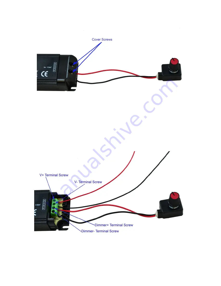
Next,
we
will
insert
the
red
driver
jumper
wire
and
black
driver
jumper
into
the
V+
and
V
‐
screw
terminals
on
the
Nano
driver.
To
do
this,
unscrew
the
V+
and
V
‐
terminals
and
remove
any
pre
‐
existing
wires
in
those
terminals.
Make
sure
not
to
unscrew
the
terminal
screws
too
much
or
the
screws
will
come
out.
Insert
the
red
driver
jumper
wire
into
the
V+
jack
and
tighten
the
terminal
screw
until
the
wire
the
terminal
when
lightly
tugged
on.
Repeat
with
the
black
driver
jumper
wire
and
the
V
‐
terminal
screw.
If
you
are
using
an
0
‐
10V
analog
controller
(ie.
Apex)
instead
of
the
potentiometer,
you
will
repeat
these
steps
for
the
D+
and
D
‐
terminal
to
remove
the
potentiometer
and
to
insert
the
positive
and
negative
dimming
wires
from
the
controller.
Consult
the
controller’s
documentation
to
identify
these
wires.
With
all
of
the
wires
attached
securely
in
the
terminals,
replace
the
cover
on
the
Nano
driver.
Repeat
these
steps
for
the
remaining
Nano
drivers.


