background image


CONTENTS 

AH-10-01 : Vector Solo SPM 

Section 1: SAFETY    


Safety Precautions  

Hazards / Safeguards  


Section 2: INTRODUCTION   


Product Description  

Specifications  


Section 3: INSTALLATION    


11 


Mounting the Control Unit  

Control Unit I/O and Ground Connections  

Vector Solo SPM Gun Connections  


Section 4: OPERATION  


13 


Operation of the Control Unit  


Section 5: SERVICE   


15 


Servicing the Vector Solo SPM Gun  


Section 6: PARTS LIST 


17 


Vector Solo SPM Gun Parts List  


Section 7: APPENDIX  


20 


Warranty Policies  

Содержание 80011

Страница 1: ...RECAUTIONS starting on page 1 and all instructions in this manual Keep this Service Manual for future reference MODEL 80011 Vector Solo SPM 80012 Power Supply Control Unit PRODUCT MANUAL AH 10 01 Vect...

Страница 2: ...2 NOTES...

Страница 3: ...ecifications Section 3 INSTALLATION 11 Mounting the Control Unit Control Unit I O and Ground Connections Vector Solo SPM Gun Connections Section 4 OPERATION 13 Operation of the Control Unit Section 5...

Страница 4: ...the WARNINGS and safety requirements for operating and servicing the equipment are followed The user should be aware of and adhere to ALL local building and fire codes and ordinances as well as NFPA...

Страница 5: ...the atomizer must be turned off prior to cleaning flushing or maintenance When using solvents for cleaning Those used for equipment flushing should have flash points equal to or higher than those of t...

Страница 6: ...m which requires correction Always turn the control panel off prior to flushing clean ing or working on spray system equipment Ensure that the control panel is interlocked with the ventilation system...

Страница 7: ...t must NOT be used in Class I Division 1 or 2 locations Electrical Discharge High voltage equipment is utilized Arcing in areas of flammable or combustible mate rials may occur Personnel are exposed t...

Страница 8: ...en training in accordance with the requirements of NFPA 33 2009 Edition Instructions and safety precautions must understood prior to using this equipment Comply with appropriate codes governing ventil...

Страница 9: ...ule alternator This position is used when no voltage is desires such as targets that exhibit Fara day cage effects The third position directs air to the infinitely adjustable air regulator then to the...

Страница 10: ...66 mm Applicator Specifications Maximum Air pressure to Applicator 7 5 bar 100 psig Maximum Fluid pressure to Applicator 7 5 bar 100 psig Applicator Weight less Cable 700 g Maximum Output Voltage 45...

Страница 11: ...ing distances required I O CONNECTIONS Connect the main air supply to the inlet of the control unit as shown below Connect the air hose to the applicator from the outlet of the control unit Appropriat...

Страница 12: ...th ground as shown in the picture below For the unit to properly function a true earth ground connection must be made Ground Connection VECTOR SOLO SPM GUN CONNECTIONS Connect fluid air and cable to t...

Страница 13: ...um of 3 5 bar 50 psig for the unit to properly function The control unit switch has three positions Each position provides a different applicator function The first position is the all functions OFF o...

Страница 14: ...an Air ON FULL VOLATGE PRODUCTION The control unit also has an infinitely adjustable atomization fan air pressure adjustment By adjusting the regulator knob the pressure to the applicator that control...

Страница 15: ...items that cannot be soaked are noted throughout this manual All electrical components cannot be cleaned or soaked in any solvents WARNING The user MUST read and be familiar with the safety instructi...

Страница 16: ...ean and undamaged NEVER soak or submerge the electrical components of the applicator i e barrel power module or handle Damage and failure may occur NEVER remove the fluid nozzle assembly while paint i...

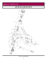
Страница 17: ...17 AH 10 01 Vector Solo SPM VECTOR SOLO SPM GUN PARTS Section 6 PARTS LIST...

Страница 18: ...18 AH 10 01 Vector Solo SPM VECTOR SOLO SPM GUN PARTS...

Страница 19: ...19 AH 10 01 Vector Solo SPM VECTOR SOLO SPM NEEDLE SHAFT PARTS...

Страница 20: ...er supplies control units etc is one 1 year from date of purchase WRAPPING THE APPLICATOR IN PLASTIC WILL VOID THIS WARRANTY ITW RANSBURG S ONLY OBLIGATION UNDER THIS WARRANTY IS TO REPLACE PARTS THAT...

Страница 21: ...21 AH 10 01 Vector Solo SPM NOTES...

Страница 22: ...Assistance 320 Phillips Ave Toledo Ohio 43612 1493 Telephone toll free 800 233 3366 Telephone 419 470 2021 Fax 419 470 2040 Technical Support Representatives can direct you to the appropriate telepho...

Отзывы: