background image


R76 Series of Tire Changers 

44


P/N 5900346 — Rev. C — Dec. 2019 

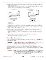
This pulls the top Bead over the Demount Lip, which is what you want. 


CAUTION


Hold on to the Bead Lifting Tool

. Depending on the Tire, it may take a 

good deal of force to move the Bead up and over the Demount Lip. If you were 

to release the Bead Lifting Tool at this point, it could easily injure the Operator 
or damage the Wheel, Tire, or the Tire Changer. 

Check to make sure the Bead Lifting Tool is lifting the Tire Bead up and over the Demount Lip of 

the Mount/Demount Head. If the Tire Bead is 

not

 coming up and over the Demount Lip, pull the 

Bead Lifting Tool out and start again. 

On some Tires, it may take multiple attempts

8.


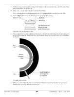
When the Bead Lifting Tool has moved all the way over to the middle of the Wheel, check the top 
Bead to make sure it is above the Demount Lip. 
The top Bead 

must

 be above the top of the Demount Lip to proceed. 

Continue holding the Bead Lifting Tool

9.


Press down and hold down the Turntable Foot Pedal; the Turntable begins turning clockwise. 

Note

:  If you have difficulty getting the Turntable to move clockwise, release the Turntable Foot 

Pedal, keep hold of the Bead Lifting Tool, and then press up on the Turntable Foot Pedal 

for few seconds to move the Turntable counterclockwise, then press down again to 

move clockwise. Repeat as necessary to clear up the difficulty. 

Watch the top Bead to make sure it is being pushed over the Rim, all the way around the Tire, as 
the Turntable moves. 

10.


Keep turning the Turntable until the entire top Bead pops over the top of the Rim. 

11.


When the top Tire Bead pops over the Rim, release the Turntable Foot Pedal and remove the Bead 
Lifting Tool. 
The top Bead is demounted. 
The next step is to demount the bottom Bead over the top Rim. 

12.


Make sure there is still lubricant on the bottom Bead and the top Rim. 
If there is not, put some more on. 

13.


Push the bottom Bead up as much as possible all the way around the Wheel, then push the side of 

the Tire opposite the Mount/Demount Head into the Drop Center of the Wheel. 
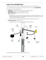
If you are using the R76ATR, you can position the Helper Disc to help hold up the Tire. If you are 

using the R76LT, you can manually lift the Tire. 

Содержание R76LT

Страница 1: ...gned and engineered in Southern California USA Made in China DANGER Read the entire contents of this manual before using this product Failure to follow the instructions and safety precautions in this...

Страница 2: ...support warranty Go to bendpak com support register your product and fill out the online form to register your product be sure to click Submit Safety Your new product was designed and manufactured wi...

Страница 3: ...airs them You can always find the latest version of the manual for your product on the Ranger website DANGER Be very careful when setting up operating maintaining or repairing this equipment failure t...

Страница 4: ...e product until you are familiar with all operating instructions and warnings Do not allow anyone else to operate the product until they are also familiar with all operating instructions and warnings...

Страница 5: ...y be used in this manual DANGER Calls attention to a hazard that will result in death or injury WARNING Calls attention to a hazard or unsafe practice that could result in death or injury CAUTION Call...

Страница 6: ...s of Tire Changers 6 P N 5900346 Rev C Dec 2019 Components The following graphic identifies the main components of the R76LT Tire Changer Front and right side views Components on left side and rear no...

Страница 7: ...Series of Tire Changers 7 P N 5900346 Rev C Dec 2019 The following graphic identifies the main components of the R76ATR Tire Changer Front and right side views Components on left side and rear not vis...

Страница 8: ...Clamps Foot Pedal Moves the Clamps to the opposite position If in they move out If out they move in Bead Break Foot Pedal Moves the Bead Breaker Blade in Inflation Foot Pedal Controls putting air int...

Страница 9: ...The steps are deflate the old Tire break the Bead secure the Wheel on the Turntable demount the old Tire mount the new Tire inflate the new Tire then remove the Wheel from the Turntable Q Can I break...

Страница 10: ...our Additional Tools No Assist Tower Bead Sealing Turbo Blast Internal Rim Clamping 10 30 in 254 762 mm External Rim Clamping 9 28 in 229 711 mm Turntable Tire Width Capacity Mounting 4 18 in 102 457...

Страница 11: ...ation Safety Rules 2 Make sure you have the necessary Tools 3 Find an appropriate Location 4 Make sure there is adequate Clearance around and above 5 Unpack the Tire Changer 6 Anchor the Tire Changer...

Страница 12: ...ers away from pinch points Safety is your top priority WARNING You must wear OSHA approved publication 3151 personal protective equipment at all times when installing using maintaining or repairing th...

Страница 13: ...ation Accessibility You need some space to move the Wheels whose Tires you are changing to and from the Tire Changer Danger When a Tire is on the Tire Changer especially during Inflation you need to k...

Страница 14: ...the Tire Changer is required WARNING The Clearance values shown below allow enough space to operate the Tire Changer For safety purposes only the Operator should be within 30 feet of the Tire Changer...

Страница 15: ...unpacking the Tire Changer as close as possible to where you are going to set it up To unpack the Tire Changer 1 At the bottom of the Cover push all of the metal tabs all the way down on all four sid...

Страница 16: ...metimes called Wedge Anchors mentioned in the following procedure are not supplied with the Tire Changer You could for example use 3 8 in diameter by 3 in long Anchor Bolts to secure the Tire Changer...

Страница 17: ...o the hole part of the way this is normal If the Anchor Bolt goes all the way in with little or no resistance the hole is too wide Once past the hole in the base the Anchor Bolt eventually stops going...

Страница 18: ...of injury or in rare cases death Additional electrical information Make sure wiring is done in accordance with National Electric Code NEC and local codes and standards covering electrical apparatus an...

Страница 19: ...the Regulator Filter You need to provide a fitting for the Air In connector it is not supplied Drawing not necessarily to scale Not all components shown The following drawing shows a quick connect ai...

Страница 20: ...changing Using non approved Tire Lubricant could corrode the Wheel or cause Tire Wheel slippage and vibration issues Be sure to use enough Tire Lubricant without using too much The point of Tire Lubr...

Страница 21: ...greased but eventually it is going to need to be re greased BendPak Ranger recommends a lithium based grease that includes molybdenum and graphite For example Extreme Pressure Moly Graph Multi Purpos...

Страница 22: ...akes changing Tires easier and helps prevent damage to the Tire and the Wheel Test the Tool Arms on the Assist Tower R76ATR only Manually move each Tool Arm separately from side to side Use the Assist...

Страница 23: ...on pressure it should be on the sidewall of the Tire Do not exceed the maximum allowed inflation pressure of the Tire Make sure the Tire is restrained for inflation either internally clamped held down...

Страница 24: ...Move away from the Tire during inflation Do not use the Tire Changer in a wet environment or expose it to rain or excess moisture If you need to use an extension cord to get power to the unit use one...

Страница 25: ...To rotate the Turntable clockwise Press down and hold down the Turntable Foot Pedal To rotate the Turntable counter clockwise Press up and hold the Turntable Foot Pedal Clamp Mechanism Each Clamp mech...

Страница 26: ...ress down on the Clamps Foot Pedal to move the Clamps out until the Wheel is being firmly held in place Note The Clamps Foot Pedal works as follows If the Clamps are in the middle of the Turntable all...

Страница 27: ...forwards or backwards Press down and release to move the Main Tower back if it is forward or forward if it is back Clamps Foot Pedal Moves the Clamps in or out Press down and release to move the Clam...

Страница 28: ...o hold the Air Chuck in place during inflation WARNING Do not hold the Air Chuck while you are inflating a Tire This leaves you close to the Tire which could result in injury if there is a problem dur...

Страница 29: ...t Demount Head in and out Control Button When pressed on the outside locks the Shaft and Slide at their current positions When pressed on the inside unlocks the Shaft and Slide Shaft Cap Use it to mov...

Страница 30: ...on Wheels The following drawing shows the location of the Demount and Mount Lips It also shows where the Tire Bead goes during demounting and mounting Side view Set Screws on other side Not necessaril...

Страница 31: ...moving After positioning the Bead Breaker Blade move away from the Bead Breaker and make sure the area is completely clear before pressing the Bead Breaker Foot Pedal The main parts of the Bead Breake...

Страница 32: ...ol to pull the Tire s Bead up and over the Mount Demount Tool to help demount the Tire You can also use the Bead Lifting Tool to push down the Tire s Bead to the left of the Mount Demount Head during...

Страница 33: ...nto the Pressurized Air Tank When closed no air can get into the tank Pressure Relief Valve Releases air pressure from the tank if the pressure gets too high Hose Moves the pressurized air from the ta...

Страница 34: ...Holds down the top Bead during mounting Upper Assist Arm Holds two Tools and the Controls The two Tools are Restraint Cone Used in two ways First when mounting a Tire use the Restraint Cone to push th...

Страница 35: ...g on the circumstances if you find damage you might want to discuss that damage with the owner of the Vehicle and or photograph the damage If you work in a shop talk to your Supervisor regarding polic...

Страница 36: ...s on the rest of the Tire Performance Wheels on some Vehicles including Corvette BMW and Lamborghini Diablo have a pressure sensor strapped to the Wheel opposite the Valve Stem On these Wheels the Bea...

Страница 37: ...the Wheel to stay in place on the Turntable The Tire Changer supports both Internal and External Clamping 4 Demount the Tire Once the Bead is broken you still have to slide both Beads of the Tire over...

Страница 38: ...re is a tool called a Valve Stem Installer Remover Tool sometimes Valve Stem Puller Remover Tool that can be used to both remove an old Valve Stem and install a new Valve Stem This tool is not the sam...

Страница 39: ...to remove the Valve Core If a tool is not available you may be able to use needle nosed pliers If you are going to use the same Valve Stem with the new Tire you are going to mount keep the Valve Core...

Страница 40: ...ce shield or goggles 2 Check the Tire again to make sure it is fully deflated 3 Check both sides of the Tire to make sure all Wheel weights from balancing have been removed If they have not remove the...

Страница 41: ...the Blade a little bit one way or the other and then try again 13 When the Bead is broken at the first spot rotate the Tire 180 and break the Bead at that location Every Tire is different With some T...

Страница 42: ...or goggles 2 Identify the Narrow side of the Tire this side goes up 3 Determine which clamping method you are going to use and move the Clamps to the starting position for that clamping method If you...

Страница 43: ...al protective equipment leather gloves steel toed work boots back belts hearing protection and ANSI approved eye protection safety glasses face shield or goggles 2 Verify that the Tire s Beads are com...

Страница 44: ...Turntable begins turning clockwise Note If you have difficulty getting the Turntable to move clockwise release the Turntable Foot Pedal keep hold of the Bead Lifting Tool and then press up on the Tur...

Страница 45: ...ble moves 17 Keep turning the Turntable until the entire bottom Bead moves over the top Rim The Tire is now dismounted and can be removed Wheel Tire Mismatches A Wheel Tire mismatch is mounting a Tire...

Страница 46: ...TPMS and adjust the Tire if necessary Do not damage the sensor Check for yellow and red dots If found line them up with the appropriate locations on the Tire Make sure the Tire is fully deflated When...

Страница 47: ...ll drop over the top of the Rim 9 Put the top Tire Bead over the Mount Lip and under the Demount Lip Side view Not necessarily to scale 10 If using the R76LT position the Bead Lifting Tool to the left...

Страница 48: ...move the Turntable clockwise If using the Bead Lifting Tool or Assist Tool to hold down the Sidewall move them around with the Tire as it rotates 15 If you run into any difficulty as the Tire rotates...

Страница 49: ...nflation process can produce noise Wear ear protection when inflating a Tire WARNING Do not exceed the maximum air pressure specified by the Tire manufacturer This increases the chances that the Tire...

Страница 50: ...a Tire This leaves you close to the Tire which could result in injury if there is a problem during inflation 4 Press and hold down the Inflation Foot Pedal for a second or two then release Air goes in...

Страница 51: ...onds you should hear a pop as the Beads are seated Bead Seating usually requires 7 psi or above Some Beads are hard to seat but never exceed 40 psi to seat the Bead If air pressure in the Tire gets to...

Страница 52: ...essure The Tire Changer has an air pressure limiter that is set at the factory so that it does not exceed 60 psi Do not override the pressure limiter DANGER Inflating a Tire with a bypassed pressure l...

Страница 53: ...r instructions Weekly Check the oil feed rate of the Oiler Lubricator It should be 1 to 2 drops per use of a pneumatic component If it is above or below this level you need to adjust it Refer to Check...

Страница 54: ...the reservoir is a quarter 25 or more filled with water you need to drain it 2 Disconnect the incoming air at the Air In connector WARNING Make sure to disconnect the incoming air and make sure it can...

Страница 55: ...each time you use the Clamps Foot Pedal Your goal is for 1 or 2 drops to come out for each use 3 If you are getting fewer than 1 or 2 drops turn the Adjustment Screw counter clockwise using a small fl...

Страница 56: ...lied cord to the power source If any issues are found have them fixed Refer to Wiring Information for additional information No air comes out when you step on the Inflate Foot Pedal Make sure the unit...

Страница 57: ...0 VAC Plug you must supply one The colors of the three exposed wires are Brown Blue and Green Yellow the European color code Important To connect the three exposed wires to an appropriate Plug or to h...

Страница 58: ...R76 Series of Tire Changers 58 P N 5900346 Rev C Dec 2019 Labels...

Страница 59: ...R76 Series of Tire Changers 59 P N 5900346 Rev C Dec 2019...

Страница 60: ...R76 Series of Tire Changers 60 P N 5900346 Rev C Dec 2019 The R76LT does not have an Assist Tower so it also does not have the labels shown on the Assist Tower in the graphic above...

Страница 61: ...R76 Series of Tire Changers 61 P N 5900346 Rev C Dec 2019 Parts Cabinet BendPak Part Drawing Description 101 Chassis body 101 Chassis body...

Страница 62: ...el support pad 5400120 115 Soap bucket 5327307 116 Plastic foot pad 5327349 117 BB return spring 3 x 25 x 23 x 140 118 Cross recessed pan head screw M3 x 10 5400119 119 Soap bucket retaining ring 120...

Страница 63: ...lation pedal bracket 163 Nut M8 164 Column limit rod 165 Tilt tower bushing 5400007 166 Fitting G1 4 8 90 169 Lock nut M4 170 Cross recessed pan head screw M4 x 35 171 Inflation regulator assembly 172...

Страница 64: ...of Tire Changers 64 P N 5900346 Rev C Dec 2019 Main Tower BendPak Part Drawing Description 5327390 200 Tilt back cylinder 200 1 Tilt cylinder connector 200 2 Tilt tower rubber spacer 200 3 Rubber sho...

Страница 65: ...0 21 Tilt tower cylinder wear strip 200 22 Fitting G1 8 8 90 200 23 Washer 201 SHCS M10 x 25 5400240 202 Hex shaft cap 5400457 203 Nut M10 NL 204 Washer 10 flat 5327416 205 Vertical shaft locking plat...

Страница 66: ...8 233 Hex shaft 234 Horizontal arm unit 234 Horizontal arm unit 234 Horizontal arm unit 234 Horizontal arm unit 5327496 237 Horizontal arm roller 238 Nut M8 239 Inner hexangular set screw M8 x 40 5327...

Страница 67: ...272 Horizontal slide stop 5327633 273 Horizontal shaft locking plate 5327524 274 Threaded rod 5327342 275 Air line guard 276 Nut M12 5530061 277 SHCS M12 x 25 5400237 278 Hex shaft spring 279 Tilt to...

Страница 68: ...omplete turntable assembly 5327713 301 Turntable unit 301 1 Plate assembly 5327300 302 Jaw clamp cylinder 5327470 302 1 Fitting 1 8 8 mm straight 5327365 302 2 Small front cylinder cover 5327487 302 3...

Страница 69: ...08 Metal bushing 5324269 309 Washer M12 SL 310 HHB M12 x 50 311 HHB M12 x 25 311 HHB M12 x 30 312 Snap Ring 65 313 Washer 12 315 Square turntable 5327450 315 1 Square turntable assembly 316 Square tur...

Страница 70: ...2019 327 1 Boat on the assembly 328 Jaw clamp inner adjustment knob 5327621 329 Jaw clamp inner adjustment pin 330 Jaw clamp pin spring 5327623 331 Jaw clamp locking pin 5327623 331 Jaw clamp locking...

Страница 71: ...of Tire Changers 71 P N 5900346 Rev C Dec 2019 Bead Breaker BendPak Part Drawing Description 5327271 400 BB cylinder 400 1 Bearing 23 x 20 x 20 400 2 Seal ring 30 x 20 x 7 400 3 Type I hole with elast...

Страница 72: ...er cylinder flange 5327437 415 Bead breaker cylinder rod 416 Fitting G1 4 10 straight 5400913 418 Washer M6 flat 419 Washer M6 flat 419 Washer 420 Nut 420 Nut 421 Double nipple G1 4 G1 4 5327561 422 S...

Страница 73: ...327097 449 Bead breaker blade 449 Bead breaker blade 449 Bead breaker blade 5327082 450 Bead breaker blade cover 5327609 452 BB bolt M14 x 95 453 Fitting G1 4 10 90 5328083 454 Bolted BB blade cover b...

Страница 74: ...joint block A 5327175 500 1 Rotary joint block 500 2 Motor assembly 500 2 Motor assembly 501 Transmission front flange 5327520 502 HHB M10 x 200 503 Oil stud 504 Washer 10 505 HHB M10 x 180 506 SHCS M...

Страница 75: ...gular set screw M6 x 20 532 Rotary joint block inner piece 532 Rotary joint block inner piece 533 O ring 60 x 2 75 534 Rotary valve jacket 534 Rotary valve jacket 5327099 535 Motor 5328429 535 Motor 5...

Страница 76: ...27545 602 1 8 Adjustable silencer 5327387 603 Tilt back air valve 5327482 603 1 Air valve O ring spacer 5327536 603 2 O ring 17 x 4 603 3 Large cylinder valve stem 5327499 603 4 Air valve end cap 5327...

Страница 77: ...2 x 25 5327038 630 Directional switch cam linkage 5400324 631 Turntable direction switch cam 632 SHCS M6 12 633 Washer 6 splick lock 634 Washer 6 flat 635 Directional switch cracket 5400331 636 Direct...

Страница 78: ...ot pedal cam cover 657 SHCS M6 x 20 658 Washer M6 flat 5400913 659 Washer M6 flat 5327047 660 Foot pedal cam 5327048 661 Foot pedal cam leaf spring left 662 Foot pedal cam leaf spring right 663 Lockin...

Страница 79: ...R76 Series of Tire Changers 79 P N 5900346 Rev C Dec 2019 Turbo Blast BendPak Part Drawing Description 701 Upper air oil reg brkt 702 Lower air oil reg brkt 703 Washer 8 Flat 704 SHCS M8 x 20...

Страница 80: ...lator assembly base 5327054 717 Tire inflator relief valve 5327055 718 Air release valve G1 4 5327769 719 Inflation gauge G1 4 5327769 719 Inflation gauge damp G1 4 5327051 720 Inflation system plasti...

Страница 81: ...le adapter 746 SHCS M4 x 12 747 Washer 4 splick lock 748 Washer 4 flat 749 Air oil regulator bracket 750 Screwed nipple G1 4 G1 4 751 Nut M6 752 Inflation hose plug 753 Fitting G1 8 8 5327044 745 Jet...

Страница 82: ...v C Dec 2019 767 PVC steel wire tube 768 PU straight pipe 5328442 754 O Ring 28 X 3 55 769 Blasting valve joint 770 Elbow 771 Butt joint 1 5328446 772 Blasting valve 773 Elbow G1 4 6 single 774 Mother...

Страница 83: ...es of Tire Changers 83 P N 5900346 Rev C Dec 2019 Assist Tower R76ATR Only BendPak Part Drawing Description 800 Assist in hand 5327567 801 Double cone BB Roller 802 Washer 20 splick lock 803 Tire pres...

Страница 84: ...2 821 Assist tower lower pin 822 Washer 12 flat 823 Snap ring 12 824 Washer 10 flat 825 Left assist tower weldment 825 Left assist tower weldment 825 Left assist tower weldment 826 SHCS M10 x 120 827...

Страница 85: ...Left assist tower cylinder rod 854 Left assist tower cylinder rod 855 Assist tower cylinder piston 855 Assist tower cylinder piston 856 O ring 14 x 2 4 856 O ring 13 2 x 2 65 857 Y ring 82 5 x 5 3 858...

Страница 86: ...18 883 Cone shaft 5400890 884 Assist arm cone 5327979 885 Assist tower bent arm plug 5327582 886 Presser arm weldment 5328283 887 Black assist top knob 888 Nut M18 5328279 889 Screw 5327075 890 Assist...

Страница 87: ...R76 Series of Tire Changers 87 P N 5900346 Rev C Dec 2019 Maintenance Log...

Страница 88: ...1645 Lemonwood Drive Santa Paula CA 93060 USA 2019 BendPak Inc All rights reserved bendpak com...

Отзывы: