background image

9

INSTALLATION

Check the appliance is electrically safe and gas sound when you have finished.

You will need the following equipment to complete the hob 
installation satisfactorily:

• 

Gas  Pressure  tester

• 

Flexible  gas  hose

• 

Multimeter

You will also need the following tools:

1. 

Electric drill

2. 

Jigsaw

3. 

Steel tape measure

4. 

Cross head screwdriver

5. 

Pencil

6. 

Adjustable spanner

7. 

Sharp knife

Checking the Parts

Check that the appliance is in a good condition after having 
removed the packaging. In case of doubt, do not use the 
appliance and contact the retailer.

The hob also has 5 individual pan supports

Never leave the packaging materials (cardboard, plastic 
bags, polystyrene foam, etc.) within children’s reach since 
they could become potential sources of danger.

Positioning the Hob

The hob should be fitted into a work surface, which is at 
least 600mm deep. In position, the hob has a maximum 
thickness of 50mm from the top of the work surface. The 
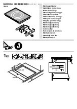
cut-out dimensions are shown in (Fig.5-1) and the minimum 
clearances in (Fig.5-2). The minimum recommended 
distances from the hob to nearby surfaces are shown in 
(Fig.5-3).

The hob should be fitted into a work surface, which is at least 
600mm deep. In position, the hob has a maximum thickness 
of 50mm from the top of the work surface, and an overall 
thickness of 100mm (120mm max depth including the gas 
connector). The cut-out dimensions are shown in (Fig.5-1)
and the minimum clearances in (Fig.5-2)

Note: If installing the hob over a standard cabinet, you may 
have to remove part of the cabinet panels to allow the unit to 
fit correctly (

see

 Fig.5-1). 

It is recommended that there is a minimum air gap of 100cm² 
underneath the hob to allow sufficient air circulation to the unit.

It is recommended that the hob be installed in a worktop with a 
minimum thickness of 40mm. If installing a built-in oven directly 
under the hob then there should be a minimum air gap of 20mm 
between the oven and the bottom of the hob.

Failure to maintain a suitable clearance may impair the 
performance of the hob.  

Any hob hood should be installed in accordance with the 
hood manufacturer’s instructions.

Surfaces of furniture and walls at the sides and rear of the hob 
should be heat, splash and steam resistant. Certain types of 

ArtNo.316-0028 - RGG77 cut-out dimensions

���

������

������

���

�����

���������������

��������������

�������������������������
��������������������������

ArtNo.316-0027 RGG77 hob clearances

�����

���

�����

���

���������

���������

��������

����

���

Fig.5-1

Fig.5-2

Fig.5-3

Содержание RGG77

Страница 1: ...RGG77 Gas Hob User Guide Installation Service Instructions U109914 03 ...

Страница 2: ...tents 1 Before You Start 1 2 Hob Overview 3 3 Cleaning Your Hob 5 4 Troubleshooting 7 5 Installation 8 6 Conversion to LPG Gas 12 7 Circuit Diagram 13 8 Technical Data 14 9 Warranty After Sales Service 15 ...

Страница 3: ...essible parts will become hot during use and will retain heat even after you have stopped cooking Keep babies and children away from the hob and never wear loose fitting or hanging clothes while the appliance is in use When the hob is not in use make sure that the control knobs are in the OFF position Always keep combustible materials e g curtains and flammable liquids a safe distance away from your...

Страница 4: ...s as a build up of fats and other foodstuffs could result in a fire Clean only the parts listed in this guide Clean with caution If a wet sponge or cloth is used to wipe spills on a hot surface be careful to avoid steam burns Some cleansers can produce noxious fumes if applied to a hot surface ...

Страница 5: ...to let the gas through to the burner The igniter should spark and light the gas If when you let go of the control knob the burner goes out then the safety device has not held in Turn the control to the off position and wait one minute then try again this time holding in the control knob for slightly longer Adjust the flame to suit by turning the control knob clockwise Fig 2 3 Ensure that the flames a...

Страница 6: ...er is designed to provide even heat over a large area Fig 2 8 It is ideal for large pans and stir frying For heating smaller pans the smaller hotplate burners may be more efficient Hob Care The burner parts can be removed for cleaning see Cleaning your hob You should wipe the top surface of the hob around the hotplate burners as soon as possible after spills occur Try to wipe any spills off while the...

Страница 7: ...hob surfaces More information is available through the Cookware Collection brochure supplied with your cooker and our website www rangemaster co uk Regular cleaning is recommended For easier cleaning wipe away any spillages immediately Hotplate Burners The burner heads and caps can be removed for cleaning Make sure they are absolutely dry before replacing them The single ring burners When refitting...

Страница 8: ...al retailers For enamelled surfaces use a cleaner that is approved fro use on vitreous enamel The Vitreous Enamel Association has a list of approved suppliers Contact them via their website www ive org uk or telephone 01527 893031 ArtNo 050 0009 Cleaning table 1 ArtNo 050 0010 Cleaning table 2 Table 3 1 Cleaning the hotplate Table 3 2 Cleaning outside the hotplate ...

Страница 9: ...not there maybe something wrong with the power supply Are the sparker ignition electrode or burner slots blocked by debris Are the burner trim and caps correctly located See the section on Cleaning Hotplate burners will not light Make sure that the burner parts have been replaced correctly after wiping or removing for cleaning Check that there is not a problem with your gas supply You can do this ...

Страница 10: ...ion Provision of Ventilation This appliance is not connected to a combustion products evacuation device Particular attention shall be given to the relevant requirements regarding ventilation In the UK The room containing the hob should have an air supply in accordance with BS 5440 Part 2 2000 All rooms require an openable window or equivalent while some rooms require a permanent vent in addition t...

Страница 11: ...ob to nearby surfaces are shown in Fig 5 3 The hob should be fitted into a work surface which is at least 600mm deep In position the hob has a maximum thickness of 50mm from the top of the work surface and an overall thickness of 100mm 120mm max depth including the gas connector The cut out dimensions are shown in Fig 5 1 and the minimum clearances in Fig 5 2 Note If installing the hob over a stand...

Страница 12: ...g a flexible hose it is essential to comply with the following instructions No part of the pipe must be able to touch parts the temperature of which exceeds 75 C The pipe must not be pulled or twisted throttled or tightly bent It must not come into contact with sharp edges or corners It must be easy to inspect the entire pipe length in order to check its state of wear The pipe must be replaced with...

Страница 13: ...e used until a replacement cover has been obtained from your supplier The colour of the correct fuse carrier is that of the coloured insert in the base of the fuse recess or stated elsewhere on the plug Always state this colour when ordering a replacement fuse carrier IMPORTANT The wires in the mains lead are coloured in accordance with the following code Green and yellow Earth Blue Neutral Brown ...

Страница 14: ...s before starting and check that the appliance is gas sound after completion Do not use reconditioned or unauthorised gas controls Disconnect from the electricity supply before commencing servicing Before electrical reconnection check that the appliance is electrically safe Injectors Remove burner caps and heads Remove the old jets Fit the new jets see Technical Data section at the back of the boo...

Страница 15: ...13 7 Circuit Diagram ArtNo 080 0016 RG70 RGG77 circuit diagram N L A B Spark generator Ignition switch DocNo 091 0002 Circuit diagram RG70 RGG77 gas ...

Страница 16: ...sures Dimensions Overall height Overall 100mm 120mm including gas connection Above worktop 50mm Below worktop 50mm Overall width 770mm see Positioning of Cooker Overall depth 510mm Space for fixing See Positioning of Cooker Minimum space above hotplate 650mm Connections Gas Electric Rp at rear right hand side 220 240V 50Hz Ratings Natural Gas L P Gas Hotplate Injector Injector Triple ring burner 3 ...

Страница 17: ...ice and the product code serial number The 2 years free maintenance for the operation of the appliance started from the date of purchase of this product Any cosmetic damage to the appliance must be reported within 90 days of delivery For in warranty service please call 0845 6035312 For general enquiries please call 0870 7895107 DocNo 111 0002 Warranty No 9 ...

Страница 18: ...16 ...

Страница 19: ...17 ...

Страница 20: ... www rangemaster co uk ArtNo 000 0003 CE logo DocNo 000 0001 Back cover Rangemaster ...

Отзывы: