

26
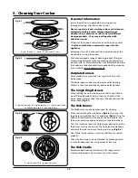
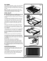
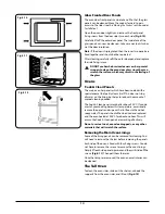
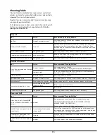
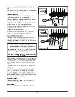
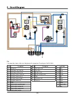
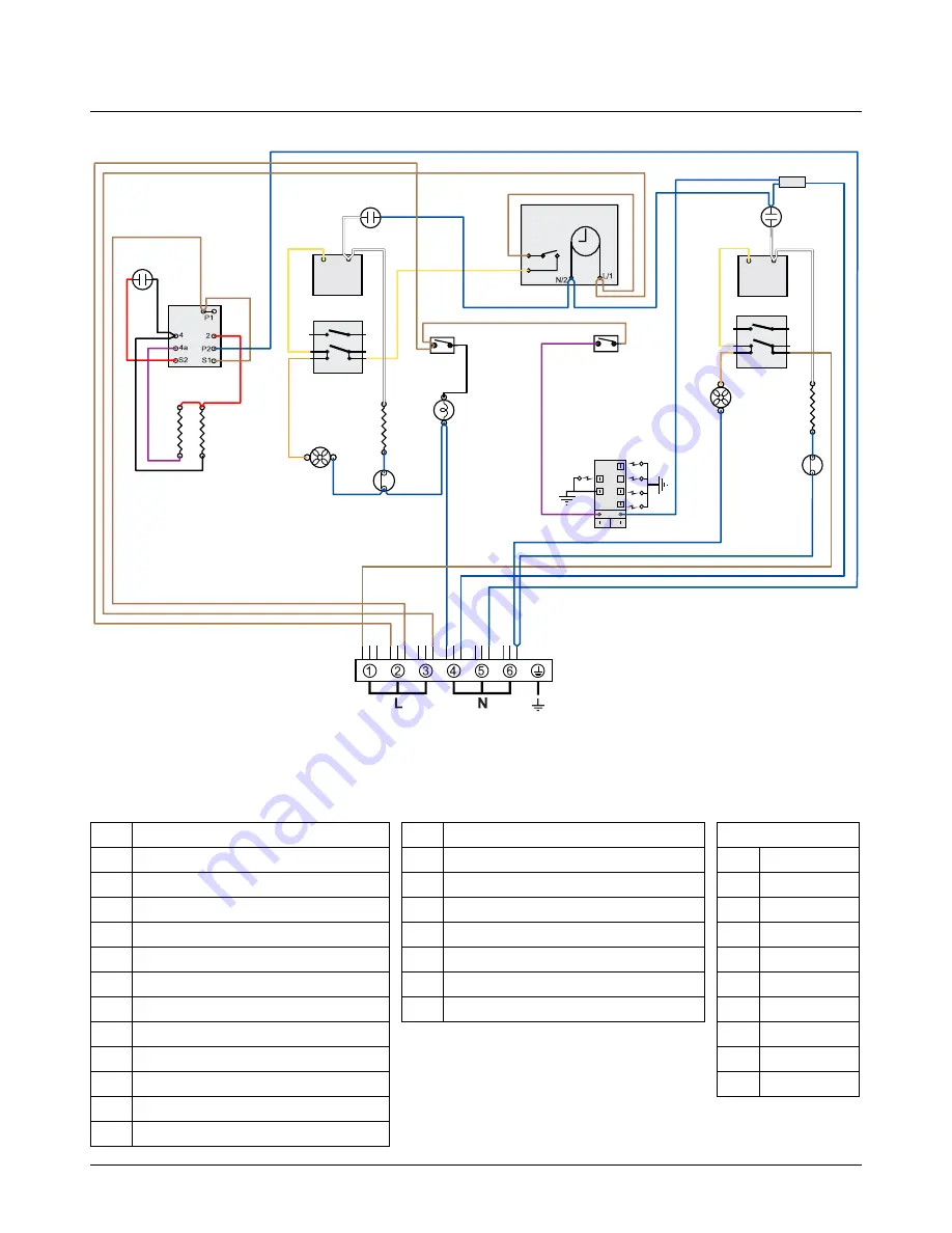
9. Circuit Diagram
a
b
e
f
c
d
1
2
�������
�
�
��
��
�
�
�
�
�
�������
�
�
��
��
�
�
�
�
��
��
��
�
�
��
��
�
�
�
��
��
�
�
�
�
�
�
�
�
�
�
� �
�
��
��
��
��
� �
�
�
�
�
�
�
�
�
��
��
�
�
�
�
��
��
��
�
�
� �
�
� �
��
�� ��
��
��
��
��
��
�
��
��
��
��
��
��
��
�
�
��
��
��
��
�
�
�
�
��
Key
The connections shown in the circuit diagram are for single-phase. The ratings are for 230V 50Hz.
Colour Code
b
Blue
br
Brown
bk
Black
or
Orange
r
Red
v
Violet
w
White
y
Yellow
g/y
Green/yellow
gr
Grey
Code
Description
A1
Grill control
A2
Grill element right-hand side
A3
Grill element left-hand side
B1
Left-hand fan oven thermostat
B2
Left-hand fan oven control
B3
Left-hand fan oven element
B4
Left-hand fan oven fan
C
Clock
D1
Right-hand fan oven thermostat
D2
Right-hand fan oven control
D3
Right-hand fan oven element
D4
Right-hand fan oven fan
Code
Description
F1
Oven light switch
F2
Oven lamp
G1
Ignition switch
G2
Ignition spark generator
H
Neon
I
Thermal cut-out
J
Connector
Содержание Professional+
Страница 30: ...28 ...
Страница 31: ...29 ...
Страница 32: ... www rangemaster co uk ArtNo 000 0003 CE logo DocNo 000 0001 Back cover Rangemaster ...


