


30
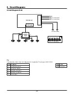
Key
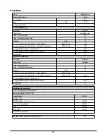
The connections shown in the circuit diagram are for single-phase. The ratings are for 230 V 50 Hz.
6
P6
5
P5
4
P4
7
P7
8
P8
2
P2
1
P1
3
P3
2
3
4
1
P3
P2
P1
P4
P033458
2
3
4
1
P3
P2
P1
P4
P033458
P038434
2
1
P2
P1
P095199
E
L
N
br
br
bk
b
w
o
br
bk
b
br
bk
b
b
b
bk
b
br
br
br
br
br
b
b
b b
bk
b
b
b
b
b
bk
v
v
v
w
b
y
o
y
br
br
y
y
y
y
v
v
r
r
br
br
br
b
r
r
b
bk
w
v
r
v
r
w
r
gr
w
bk
o
o
y
br
br
bk
b
v
b
b
br
br
br
o
w
y
b
b
b
r
o
b
b
b
br
w
b
bk
gr
w
v
b
r
r
r
y
y
br
r
r
b
w
b
b
br
br
b
br
A2
A1
B1
A3
B2a
B4
B2
B5
B6
B7
F2
D2
I
F3
F4
K
J
I
H
F1
D1
K
K
C
B3
J
J
K
G
K
D3
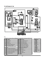
Code Description
A1
Grill thermostat
A2
Grill elements
A3
Grill front switch
B1
Multi-function oven thermostat
B2
Multi-function oven control
B2a
Multi--function oven thermostat front
switch
B3
Multi-function oven base element
B4
Multi-function oven top element (outer pr.)
B5
Multi-function oven top element (inner pr.)
B6
Multi-function oven fan element
B7
Multi-function oven fan
C
Clock
Code Description
D1
Slow cook oven thermostat
D2
Slow cook oven switch
D3
Slow cook oven elements
F1
Right-hand oven thermostat
F2
Right-hand oven switch block
F3
Right-hand fan oven element
F4
Right-hand fan oven fan
G
Cooling fan
H
Oven light switch
I
Oven light
J
Thermal cut-out
K
Neon
Code Colour
b
Blue
br
Brown
bl
Black
or
Orange
r
Red
v
Violet
w
White
y
Yellow
g/y
Green/yellow
gr
Grey
Circuit Diagram: Oven
Содержание Excel 110 G5 Induction
Страница 1: ...Excel 110 G5 Induction Britain s No 1 Range Cooker USER GUIDE INSTALLATION INSTRUCTIONS...
Страница 4: ...ii...
Страница 38: ...34 Notes...