background image

INSTALLATION


Check the appliance is electrically safe and gas sound when you have finished.

21

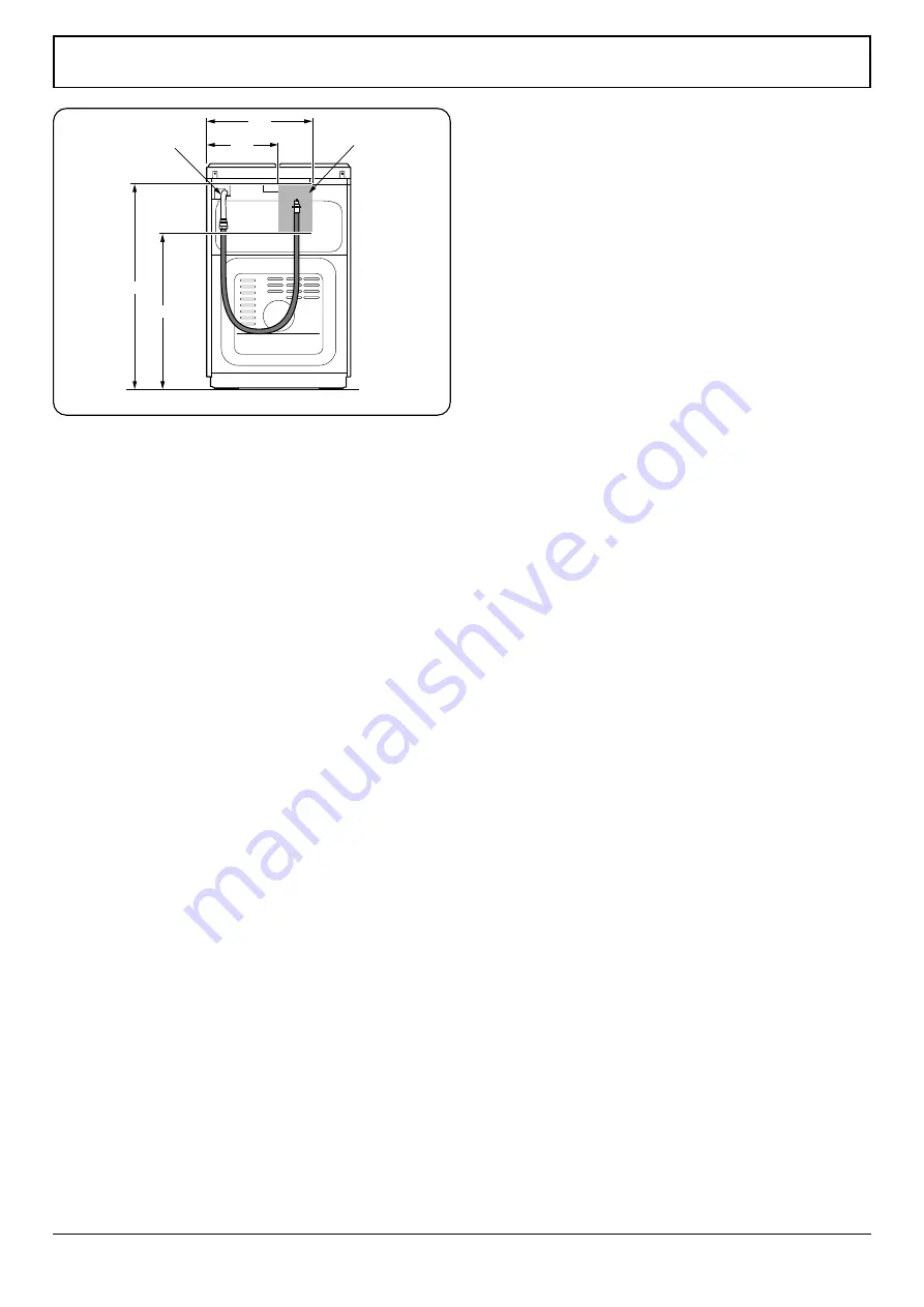
All dimensions in millimetres

800

600

A

400

300

Gas inlet block

Fig. 7.5 

Points that must be checked during 
fixed gas connection assembly

The method used to assemble a fixed gas connection (gas 

connection made by threads, e.g. a nut) varies according 

to the country you are in. The most common parts for your 

country will be supplied with your appliance. Any other parts 

required can be supplied as spare parts.
During connection, always keep the nut on the gas manifold 

fixed while rotating the counter-part. Use appropriately-

sized spanners for a safe connection. For surfaces between 

different components always use the seals provided in the 

gas conversion kit.
The seals used during connection should also be approved 

to be used in gas connections. Do not use plumbing seals for 

gas connections.
Remember that this appliance is ready to be connected to the 

gas supply in the country for which it has been produced. 
The main country of destination is marked on the rear cover 

of the appliance. If you need to use it in another country, any 

of the connections in the figure below may be required. In 

such a case, contact local authorities to learn the correct gas 

connection.
The Cooker must be installed and maintained by a suitably 

qualified gas registered technician in accordance with current 

safety legislation.


n

WARNING: Do not use a naked flame to check for gas 

leaks.

Electrical Connection

All external wiring must comply with the IEE Regulations 

for the Electrical Equipment of Buildings. Connection to the 

electrical supply is via a plug and socket. 


n

WARNING: The electrical connection of this 

appliance should be carried out by an authorised 

service person or qualified electrician, according to 

the instructions in this guide and in compliance with 

the current local regulations. 


n

WARNING: THE APPLIANCE MUST BE EARTHED. 

• 

Before connecting the appliance to the power supply, 

the voltage rating of the appliance (stamped on the 

appliance identification plate) must be checked for 

correspondence to the available mains supply voltage, 

and the mains electric wiring should be capable of 

handling the appliance’s power rating (also indicated on 

the identification plate). 

• 

During installation, please ensure that isolated cables 

are used. An incorrect connection could damage your 

appliance. If the mains cable is damaged and needs to 

be replaced this should be done by a qualified person. 

• 

Do not use adaptors, multiple sockets and/or extension 

leads. 

Содержание Classic 60 Gas

Страница 1: ...Classic 60 Gas Professional 60 Gas User Guide Installation Service Instructions U111323 02a...

Страница 2: ......

Страница 3: ...oking Tips 11 5 Cleaning Your Cooker 12 Hotplate Burners 12 The Griddle 12 Grill 12 Control Panel and Doors 13 Oven Door Panel 13 Ovens 13 6 Troubleshooting 16 7 Installation 18 Dear Installer 18 Safe...

Страница 4: ......

Страница 5: ...specified otherwise in this guide n Stabilizing brackets must be installed in order to prevent tipping of the appliance Peculiar smells When you first use your cooker it may give off a slight odour T...

Страница 6: ...ds n DO NOT use aluminium foil to cover shelves linings or the oven roof n NEVER heat unopened food containers Pressure build up may make the containers burst and cause injury n DO NOT use unstable sa...

Страница 7: ...r that knob controls Each burner has a Flame Supervision Device FSD that prevents the flow of gas if the flame goes out To ignite a hotplate burner push in and turn the associated control knob counter...

Страница 8: ...art Pans and kettles with concave bases or down turned base rims should not be used Fig 2 5 Simmering aids such as asbestos or mesh mats are NOT recommended Fig 2 6 They will reduce burner performance...

Страница 9: ...d the griddle for the gases to escape n NEVER fit two griddles side by side After cooking allow the griddle to cool before cleaning The Top Oven After you ignite the oven burner you can adjust the tem...

Страница 10: ...r polished steel trays reflect the heat away and reduce base browning When cooking more than one dish in the oven place dishes centrally on different shelves rather than cluster several dishes on one...

Страница 11: ...te temperature for each position is displayed in Table 2 1 Preheating Operation The Top Oven Gas Push in and turn the control knob counter clockwise to select the MAX position as indicated on the knob...

Страница 12: ...orm with heat Once they have cooled down they will recover their original appearance and performance Trays and wire grids can be positioned on any level from 1 to 4 Please note Level is 3 recommended...

Страница 13: ...9 5 4 3 2 1 2 3 1 4 Grill pan handle Grill pan Fig 2 14 Fig 2 15 Fig 2 16 Fig 2 17 Fig 2 18 Fig 2 19...

Страница 14: ...nd and the symbol will flash on the display Press any key to stop the audible warning and the symbol will disappear n REMEMBER Turn the oven control knob s to 0 Audible warning time adjustment The aud...

Страница 15: ...ced centrally on the shelf and there is sufficient room around the baking tray dish to allow for maximum circulation To reduce fat splashing when you add vegetables to hot fat around a roast dry them...

Страница 16: ...ediately dry them with a kitchen towel After cleaning ensure they are re assembled correctly Fig 5 1 The Griddle Always clean the griddle after use Allow it to cool completely before removing Immerse...

Страница 17: ...rp metal scrapers to clean the oven door glass since they can scratch the surface which may result in shattering of the glass Ovens Cleaning the Inside of the Oven Fig 5 6 The inside of enamelled oven...

Страница 18: ...ry it Wash and rinse the hob burner caps Do not leave them wet Dry them immediately with a dry cloth Make sure you re assemble all parts correctly after cleaning The surfaces of the pan supports may b...

Страница 19: ...lcohol stain removers degreasers surface abrasive chemicals Otherwise corrosion may occur on the powder painted surfaces and stains may occur The manufacturer will not be held responsible for any dama...

Страница 20: ...t setting being used Supply gas pressure may not be correct Check that the recommended temperatures and shelf positions are being used Be prepared to adjust the temperature up or down slightly to achi...

Страница 21: ...r caught between the timer buttons Touch model there is moisture on the control panel The key lock function is set Remove the foreign matter and try again Remove the moisture and try again Check wheth...

Страница 22: ...er recycling in accordance with the regulations etc Instructions for the Installer Ventilation requirements For rooms with a volume of less than 5 m3 permanent ventilation of 100 cm2 free area is requ...

Страница 23: ...It is recommended that there is at least 20mm space between the back cover of the cooker and the wall for air circulation Fig 7 3 Adjacent kitchen furniture must be heat resistant to 90 C General inst...

Страница 24: ...n If the pressure of used gas is different than the values stated or is not stable in your area it may be necessary to assemble an available pressure regulator on the gas inlet You should contact an a...

Страница 25: ...w may be required In such a case contact local authorities to learn the correct gas connection The Cooker must be installed and maintained by a suitably qualified gas registered technician in accordan...

Страница 26: ...The terminal box connection is placed on the terminal box Three pin plugs to BS1363 with a capacity of not less than 13A must be used and fitted with a 13 amp fuse ASTA approved to BS1362 You must ref...

Страница 27: ...feet clockwise It is possible to raise the height of the appliance up to 30 mm by adjusting the feet The appliance is heavy and we recommend that a minimum of 2 people lift it Never drag the appliance...

Страница 28: ...ectricity supply before servicing n Before electrical reconnection check that the appliance is electrically safe Changing injectors Hob burners Cut off the main gas supply and unplug the appliance fro...

Страница 29: ...ning the minimum flame position To determine the minimum position ignite the burners and leave them on in the minimum position Remove the knobs to gain access to the screws With the help of a small sc...

Страница 30: ...in the correct way on the burner body n Check the appliance is gas sound n Check operation of all the burners Assembly of gas supply and leakage check Connect the appliance in accordance with applicab...

Страница 31: ...Upper Black Black Black Limiter Thermostat Thermostat Lamp Brown Blue Blue Brown Brown Brown Brown Digital Timer Brown Brown Brown Brown Microswitch Blue Blue Blue Blue Blue Oven Lamp Oven Lamp Button...

Страница 32: ...Electric Natural gas 20mbar 230 400V 50Hz Butane 29mbar Propane 37mbar Dimensions Overall height minimum 895mm maximum 925mm Overall width 600mm Overall depth 600mm to fascia inc splashback 610mm ove...

Страница 33: ...4 57 Energy Efficiency of Hob 58 3 This hob complies with EN 30 2 1 Main Oven Burner NG G20 20 mbar LPG G30 G31 28 30 37 mbar Dia of injector 1 100mm 115 75 Nominal rating kW 2 4 2 4 Consumption 228...

Страница 34: ...t source Gas Volume Litres 71 Energy consumption gas conventional MJ cycle 5 29 kWh cycle 1 47 Energy consumption gas forced air convection MJ cycle kWh cycle Energy Efficiency Index conventional 79 5...

Страница 35: ...31 NOTE...

Страница 36: ...32 NOTE...

Страница 37: ...33 NOTE...

Страница 38: ......

Страница 39: ......

Страница 40: ...w rangemaster co uk DocNo 000 0001 Back cover Rangemaster Clarence Street Royal Leamington Spa Warwickshire CV31 2AD England Tel 44 0 1926 457400 Fax 44 0 1926 450526 E mail consumers rangemaster co u...

Отзывы: