


Manual-4
Audio Connections
As a safety precaution, turn all devices (especially power
amplifiers) OFF when making connections. Doing so gives you a
chance to find and correct wiring mistakes and prevent damage
to your amplifiers, speakers, ears, etc.
Analog Inputs and Outputs
The RPM 44 has four balanced analog Inputs and four bal-
anced analog Outputs.
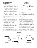
For each Input or Output Euroblock connector:
• Connect the (positive) audio line to the ‘+’ terminal.
• Connect the (negative) audio line to the ‘–’ terminal.
• Connect the cable shield to the ground terminal.
For those installations where the RPM 44’s internal shield-
to-chassis connection causes interference, connect each shield
directly to the chassis PEM nut located above each Euroblock
connector, keeping the shield wrapped around the audio conduc-
tors as much as possible.
For optimum Electromagnetic Interference (EMI) immunity,
connect the shields at both ends of the cable. See RaneNote 110
“Sound System Interconnection” for more information on system
connections and proper grounding practices.
Analog Input Stage
The analog input uses a two-stage gain approach. The first
stage contains a software controlled analog line/mic pad and
switchable-gain preamp. The second stage contains a Digital
Trim control located immediately after the A/D converter.
The RPM 44 takes the following approach to input clipping:
If you’ve set the Analog Gain so the input stage is not clip-
ping, it is not possible to clip the A/D converter, since there is no
additional gain between the initial input stage and the A/D con-
verter. The Digital Trim control, located after the A/D converter,
can be set to clip the signal to your heart’s content, so adjusting
this trim to provide the hottest signal to the DSPs
without
clip-
ping is the most important step when setting up gain structure.
For this reason, a dedicated meter displaying the signal level be-
ing passed to the DSPs is provided in each Analog Input block.
If the DSPs are working with a clipped signal, the audio is (as
expected) distorted and none too pretty, but it is not a drastic,
damaging sound. And while it’s technically possible to write a
DSP algorithm to emulate the glorious clipping distortion of
vacuum tubes, it’s not particularly useful for an installed sound
system, where the DSP power could be put to better use remov-
ing that annoying 500 Hz feedback from the Pope’s podium mic.
Plus, they don’t yet make DSP chips with gold-plated substrates
for those celestial highs and that moist, supple midrange.
Analog Output Stage
Each analog output also uses a two-stage gain approach,
which differs slightly from that of the analog input stage. The
first stage is a Digital Trim control located immediately
before
the D/A converter. The second stage is an analog trim control
located immediately
after
the D/A converter. Attenuation is han-
dled in the analog domain, while boosting (when the incoming
digital signal is low) is handled in the digital domain. Boosting
and attenuating using this two-stage approach helps maintain
the RPM 44’s excellent noise performance.
Digital (AES3) Input and Output
AES3 is a popular 2-channel (stereo) digital audio inter-
face commonly found on professional digital audio equipment
(digital mixers, DAT machines, etc.). Each channel of the AES3
digital stream is treated independently within the RPM 44.
See the RaneNote “Interfacing AES3 and S/PDIF”, available
from Rane’s web site (www.rane.com/library.html), for more
information about interfacing consumer S/PDIF gear to the
professional AES3 standard.
Use the AES3 I/O to:
• Connect multiple RPM 88/44/22/26z’s together to create a
2-channel digital “bus” between devices.
• Connect directly to the AES3 output of a digital mixing
console.
• Connect directly to the AES3 input of a DAT machine for
recording purposes.
• Connect to an external A/D or D/A converter, effectively add-
ing two more analog inputs or outputs.
Incoming Sample Rate and Word Length
The AES3 input has a built-in sample rate converter capable
of accepting incoming sample rates up to 96 kHz. Sample
rates exceeding the RPM 44’s internal 48 kHz sample rate are
automatically downsampled. Word lengths up to 24-bits are
accepted.
Outgoing Sample Rate and Word Length
The AES3 output uses a fixed 48 kHz sample rate and 24-bit
word length.