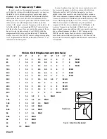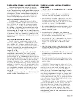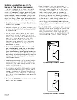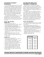
Manual-9
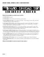
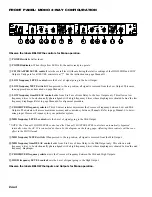
4. Now press in the MID MUTE switch on the crossover so
that the tone is removed from the mid driver. Without
re-adjusting either the meter or the crossover input or mid
frequency level controls, turn up the HIGH LEVEL control
until the tone coming from only the high driver reads 0 dB
on the SPL meter.
5. Now release the MID MUTE switch so that the tone is
emitted from both the high and mid drivers. Check the
reading on the SPL meter:
i. If the meter reads +3 dB, then the drivers are properly
phase aligned and no delay is necessary; leave the MID
DELAY control at full minimum.
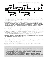
ii. If the meter reads less than +3 dB, slowly turn up the
MID DELAY control until the meter just reads +3 dB.
Now the drivers are electronically phase aligned and the
DELAY control should be left in this position at all
times, unless the speaker system is physically altered.
iii. If you have turned the MID DELAY control all the way
up and still do not obtain a +3 dB reading, you will have
to physically move the high driver farther forward until
the SPL meter reads +3 dB. The amount of displacement
corrections available from the delay depends on the
actual crossover frequency: the higher the frequency the
less amount of correction capability. If the drivers are
built into a single cabinet and/or it is impossible to
change relative positions, then you will have to obtain
additional delay to achieve proper phase alignment.
iv. If turning the MID DELAY control up makes the SPL
reading decrease instead of increase, this means that the
high driver is actually in front of the mid driver; adding
delay to the mid driver then only worsens the situation.
There are a couple of ways to deal with this:
a. Try to move the high driver back as far as possible
without losing stability in balancing the speaker stack.
You may want to raise it up as well to restore disper-
sion close to the stack. If you cannot move the high
driver, then you will have to obtain an additional
external delay source to align the high and mid
drivers. The built-in delay system in the AC 22 is
designed to accommodate the majority of common
speaker configurations; if you encounter confusion or
difficulty with your particular system, it is best to
consult your dealer or the Rane factory for assistance.
b. If this decrease in the display due to the LOW
DELAY control occurs at a low frequency crossover
point below about 150 Hz, set the DELAY control to
minimum and leave it there. Frequencies below 150
Hz are actually omnidirectional, so that phase
misalignment is virtually inaudible below this point.
Subwoofers will often possess long folded or straight
horns, resulting in the diaphragm being well behind
the rest of the stack. Most authorities agree that phase
alignment of subwoofers is unnecessary. Otherwise
you will have to obtain additional delay equipment to
align these to the rest of the system.
6. Tune the tone generator to the next lower crossover
frequency and then repeat steps 2 through 5, using the
appropriate level and delay controls. Once the DELAY
control is set, you may re-adjust any of the crossover
LEVEL controls at the beginning of each alignment
procedure. Once all of the DELAY controls are set, then
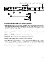
re-adjust the output LEVEL controls as outlined on page
Manual-11.


