About the Frontend Control option
R&S
®
SMW-K553
10
User Manual 1179.4240.02 ─ 02
required IF cable between the R&S
SMW and the external frontend is not as vul-
nerable to distortion effects and power loss. Furthermore, since the IF cable is usu-
ally part of the fixed setup, any existing frequency response can be calculated in
advance. The R&S
SMW can then adapt signal generation automatically.
A typical application is a test involving a DUT placed in an RF shield box, see
on page 10. The external frontend is connected directly to the
RF shield box, while the R&S
SMW and R&S
FSV/A are placed in a measurement rack
elsewhere in the laboratory.
2.3
Test setup
The R&S
SMW supports the following external frontend types:
●
R&S FE44S
●
R&S FE50DTR
For details, see the data sheet of the R&S
SMW.
OTA microwave test setup
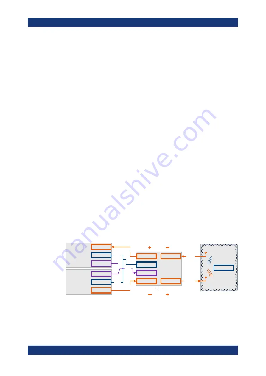
You can use an external frontend, e.g., for over-the-air (OTA) microwave testing.
illustrates an example of a test setup including a vector signal generator, an
external frontend, a DUT inside an RF shield box and a vector signal analyzer.
The signal generator provides the IF signal and the reference signal to the external
frontend. The signal analyzer can also provide the reference signal. All instruments are
connected to the same LAN. The signal generator or signal analyzer control the exter-
nal frontend via LAN using a secure sockets layer (SSL) connection, see
The external frontend up-converts the IF signal from the signal generator and transmits
the RF signal to the DUT (Tx mode). The DUT receives the RF signal and responds by
transmitting an RF signal to the external frontend. The frontend down-converts the RF
signal to an IF signal and transmits the IF signal to the signal analyzer (RX mode).
Vector signal
analyzer
Vector signal
generator
RF
Ref Out
Ref Out
RF
LAN
IF In
Ref
IF Out
IF Out A
LAN
IF In B
RF A
RF B
Ref In
LAN
LAN
LAN
DUT
RF shield box
RF Out
RF In
R&S
FE50DTR
Rx mode
Tx mode
Figure 2-1: Typical setup using an external frontend
Test setup


