Connecting the probe
R&S
®
RT
‑
ZM
22
User Manual 1419.3128.02 ─ 05
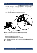
To connect the probe tips to the probe amplifier
1. Connect the probe to an oscilloscope channel to ensure that the amplifier is
grounded.
2. Push the tip module straight in the probe amplifier to connect them.
To disconnect the probe tips from the probe amplifier
►
NOTICE!
Risk of damaging the device. Do not bend the probe tip module to
pop it loose from the amplifier. Do not wiggle the probe tip module up and
down or twist it to remove the connector from the probe amplifier.
Pull the tip module connectors straight out of the sockets.
3.4.2
Considerations for soldering
For best measurement results and to avoid damaging the probe, observe the fol-
lowing when soldering in the probe tips:
●
Always disconnect the probe tip module from the probe amplifier before unsol-
dering or disconnecting it, moving it to a new position and resoldering or
reconnecting it.
●
Do not leave the soldering iron in contact with the probe tip for more than a
few seconds at a time. Excess heat can damage the probe.
●
Some solder-in accessories are very fine and sensitive. Stabilize the probe
using appropriate means (e.g. adhesive pads, probe positioner) to protect the
solder joint from excessive mechanical stress.
●
Always keep soldered leads as short as possible for best performance and
signal integrity.
3.4.3
R&S
RT
‑
ZMA10 tip cable solder-in
The R&S
RT
‑
ZMA10 tip cable solder-in is a semi-permanent solder-in connection
that supports the full bandwidth of the probe amplifier. It is well suited for creating
solid contact with test points that are hard to reach (e.g. IC pins).
Connecting the probe to the DUT


