


Measurement Principles
R&S
®
RT
‑
ZD10/20/30
50
User Manual 1410.4550.02 ─ 05
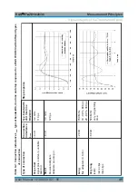
As a result, there are different opinions which signal is the better output of the
probe:
●
The initial signal that is not loaded by the probe (V
S
), and that corresponds to
the signal at the test point without the probe being connected.
●
The input signal that is loaded with the input impedance of the probe (V
in
) and
that is present between the probe tips.
Both approaches are physically correct and have their individual advantages and
disadvantages. In theory, it is even possible to convert mathematically the two
measurement results into each other, but conversion is a complex transformation
to and from the frequency domain. Probe manufacturers use one or the other of
these two approaches.
Rohde & Schwarz has decided in favor of the user-friendly approach. In our opin-
ion, most users want to know the signal present in the DUT before it was altered
by the influence of the probe. Their goal is to characterize the DUTs, not the
probe.
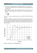
If measurements are carried out in a 100
Ω (or a comparable) environment, the
signal displayed on the oscilloscope screen is always a direct representation of
the unloaded signal VS, see
Figure 6-8: Unloaded and loaded input signal and step response (for RT-ZS30)
Probing Philosophy