


R&S
RT
‑
ZA15 External Attenuator
R&S
®
RT
‑
ZD10/20/30
24
User Manual 1410.4550.02 ─ 05
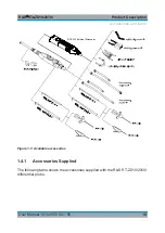
3.2
Description
The R&S
RT
‑
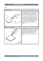
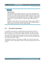
ZA15 external attenuator with inserted R&S
RT
‑
ZD10/20/30 is
shown in
1
3
4 5
7
2
6
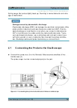
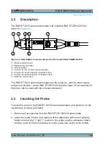
Figure 3-1: R&S
RT
‑
ZA15 external attenuator with inserted R&S
RT
‑
ZD10/20/30
1 = Positive signal socket
2 = Negative signal socket
3 = Ground socket
4 = Trimmer for DC common mode rejection
5 = Trimmer for pulse response of positive input
6 = Trimmer for pulse response of negative input
7 = Notch for micro button
The R&S
RT
‑
ZA15 external attenuator has the same tip - and the same signal
and ground sockets - as the R&S
RT
‑
ZD10/20/30 probe head. All accessories for
the probe can be used with the external attenuator.
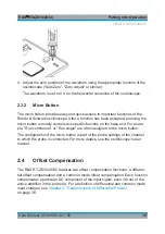
3.3
Inserting the Probe
To insert the probe in the R&S
RT
‑
ZA15 external attenuator and enable it on the
oscilloscope proceed as follows.
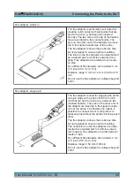
1. Remove all accessories from the R&S
RT
‑
ZD10/20/30 probe head.
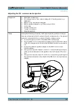
2. Insert the probe into the rear opening of the attenuator with correct polarity.
Make sure that the "+" and "-" marks on the probe and the attenuator match,
and the notch for the micro button is on the same side as the micro button.
Inserting the Probe