background image

R&S

®

RT

ZD10/20/30

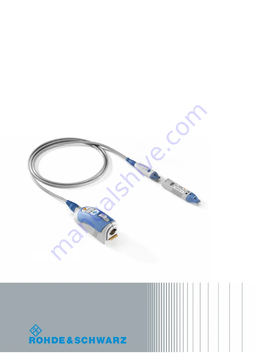
Active Differential Probe

R&S

®

RT

ZA15


External Attenuator

User Manual

User Manual

Version 05


1410455002

(>:]À2)

Содержание RT-ZA15

Страница 1: ...R S RT ZD10 20 30 Active Differential Probe R S RT ZA15 External Attenuator User Manual User Manual Version 05 1410455002 2...

Страница 2: ...9 0 Fax 49 89 41 29 12 164 Email info rohde schwarz com Internet www rohde schwarz com Subject to change Data without tolerance limits is not binding R S is a registered trademark of Rohde Schwarz Gmb...

Страница 3: ...2 3 Using the Probe 17 2 4 Offset Compensation 18 3 R S RT ZA15 External Attenuator 23 3 1 Key Characteristics 23 3 2 Description 24 3 3 Inserting the Probe 24 3 4 Adjusting 25 4 Connecting the Probe...

Страница 4: ...al 1410 4550 02 05 7 Maintenance and Service 51 7 1 Cleaning 51 7 2 Contacting Customer Support 51 7 3 Returning for Servicing 52 7 4 Calibration Interval 53 7 5 Discarding the Product 53 7 6 Spare Pa...

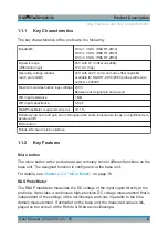
Страница 5: ...a wide variety of devices under test DUT Provided with special features such as the R S ProbeMeter and the micro button the R S RT ZD10 20 30 is designed to meet tomorrow s challenges in probing The...

Страница 6: ...nt error 0 1 Extremely low zero and gain errors throughout the entire temperature range no significant tem perature drift Micro button Rohde Schwarz probe interface 1 1 2 Key Features Micro button The...

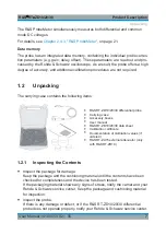
Страница 7: ...llowing items R S RT ZD10 20 30 differential probe Carrying case Accessory boxes User manual R S RT ZD10 20 30 data sheet Calibration certificate Documentation of calibration values if ordered R S RT...

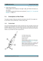
Страница 8: ...mall and lightweight probe head is designed for easy handling and high per formance measurements The probe head is used for connecting the probe and the DUT Different accessories for the signal and gr...

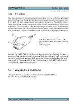
Страница 9: ...sures that it will be possible to operate future probes on any base unit that features a Rohde Schwarz probe interface 1 Rohde Schwarz probe interface with 7 mm 276 mil coaxial connector and 6 pogo pi...

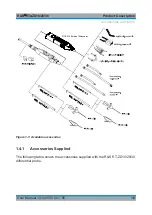
Страница 10: ...10 User Manual 1410 4550 02 05 RT ZA15 External Attenuator Figure 1 1 Available accessories 1 4 1 Accessories Supplied The following table shows the accessories supplied with the R S RT ZD10 20 30 dif...

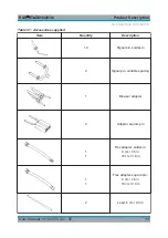
Страница 11: ...essories supplied Item Quantity Description 10 Signal pin solder in 4 Signal pin variable spacing 1 Browser adapter 2 Adapter square pin 1 1 Flex adapter solder in 4 cm 1 6 in 10 cm 3 9 in 1 1 Flex ad...

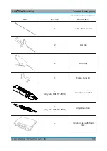
Страница 12: ...nual 1410 4550 02 05 Item Quantity Description 1 Lead 15 cm 5 9 in 2 Mini clip 2 Micro clip 1 Marker band kit 1 only with R S RT ZD10 External attenuator 1 only with R S RT ZD10 Adjustment tool 1 Carr...

Страница 13: ...ble 1 4 R S RT ZA6 lead set Item Quantity Description Lead 6 cm 2 4 in Lead 15 cm 5 9 in 5 5 Contains short and long leads Table 1 5 R S RT ZA7 differential pin set Item Quantity Description Signal pi...

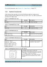
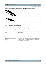
Страница 14: ...following accessories are available Table 1 8 Service accessories Item Description R S RT ZK2 The service kit is used to calibrate the probe to do perform ance tests and for servicing The service kit...

Страница 15: ...ground The maximum input voltage is derated for higher frequen cies Refer to the data sheet for further information Risk of device damage The R S RT ZD10 20 30 can withstand a moderate amount of phys...

Страница 16: ...ou connect or disconnect a DUT or test fixture to the probe and to the instrument s test ports To pre vent electrostatic discharge use a wrist strap and cord and connect your self to the ground or use...

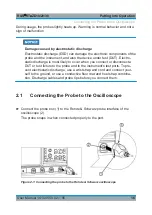
Страница 17: ...your oscilloscope 2 3 Using the Probe 2 3 1 Zero Adjustment The zero error can impair the measurement results therefore correct the zero error if necessary The zero error of the probe itself is very...

Страница 18: ...n the base unit For exam ple Run continuous or Run single are often assigned to the micro button The configuration of the micro button is part of the probe settings of the channel to which the probe i...

Страница 19: ...es setting a differential offset compensation is directly visible on the oscilloscope screen as a voltage offset of the measured waveform Figure 2 2 Differential offset compensation for a single ended...

Страница 20: ...input sockets referenced to the ground socket This is particularly helpful for measurements on differential signals with high common mode levels for example current measurements using a shunt resistor...

Страница 21: ...r precision compared to the oscilloscope s DC accuracy The DC measure ment is performed continuously and in parallel to the time domain measurement of the oscilloscope High precision measurements are...

Страница 22: ...ement mode and gain Unique way to detect unexpected or inadmissible common mode voltages e g bias points measurement of common mode DC voltages without recon necting the probe Differential measurement...

Страница 23: ...h R S RT ZD10 DC to 1 5 GHz with R S RT ZD20 DC to 2 0 GHz with R S RT ZD30 Dynamic range differential input 50 V with 50 V offset capability Differential input resistance 1 M Differential input capac...

Страница 24: ...nput 7 Notch for micro button The R S RT ZA15 external attenuator has the same tip and the same signal and ground sockets as the R S RT ZD10 20 30 probe head All accessories for the probe can be used...

Страница 25: ...information refer to the user manual of your oscilloscope When you use the probe together with the external attenuator hold them at the gripping section of the external attenuator to ensure optimal me...

Страница 26: ...i output of the DC voltage source The ground socket is connected to the Lo output of the DC voltage source Connect the probe to CH1 of the R S RTO oscilloscope Plug the BNC to 4 mm dual banana adapter...

Страница 27: ...etup Source Ch1 Main Measurement Mean State On Vertical menu Probe Setup Ch tab Attenuator RT ZA15 Vertical menu Channels Ch1 Offset 0 V Position 0 div Adjustment Set the voltage of the DC voltage sou...

Страница 28: ...robe Setup Ch tab Attenuator RT ZA15 Using the lead and a mini clip connect the negative input of the exter nal attenuator to the ground clamp of the R S RTO oscilloscope Press the positive input of t...

Страница 29: ...f the negative input Using the lead connect the positive input of the external attenuator to the ground clamp of the R S RTO oscilloscope Press the negative input directly to the square wave signal cl...

Страница 30: ...of injuries The included probe pins are exceptionally sharp and must be handled with extreme care To prevent injuries always use tweezers when inserting or removing pins Some solder in accessories are...

Страница 31: ...h small contact points such as SMT components or IC pins The wires have an additional insulating finish in order to prevent unwanted shorts There is no need to strip the wires because the finish disso...

Страница 32: ...e range 2 54 mm 100 mil Browser adapter The spring loaded browser adapter allows handheld probing with maximum convenience Because it compensates for minor uneven ness and movements it is capable of e...

Страница 33: ...6 in and 10 cm 3 9 in Distance range 0 mm to 12 mm 0 mil to 470 mil Do not use the flex adapter at voltages beyond 30 V Flex adapter square pin The flex adapter is used for plugging the probe onto pi...

Страница 34: ...can be used to connect either the signal sockets or the ground socket In addition it allows micro and mini clips to be connected to the probe Length Short lead 60 mm 236 mil Long lead 150 mm 591 mil...

Страница 35: ...S RT ZD10 20 30 35 User Manual 1410 4550 02 05 Micro clip The micro clip is designed for probing IC pins and thin wires in fine pitch applications The micro clip fits directly into the signal socket...

Страница 36: ...etween the positive and negative signal sockets Positive single ended input voltage Vp Voltage between the positive signal socket and the ground socket Negative single ended input voltage Vn Voltage b...

Страница 37: ...nds only on the differential input voltage Vin between positive and negative input and suppresses the com mon mode voltages This is equivalent to an infinite common mode rejection ratio CMRR In contra...

Страница 38: ...ge or differential mode range designates the maximum dif ferential voltage Vin that may occur between the positive and negative signal pin At the same time the two voltage values at each of the two si...

Страница 39: ...Pro beMeter is a convenient way to detect breaches of the operating voltage window owing to excess DC common mode voltages 5 3 Ground Connection It is typically not necessary to connect the ground soc...

Страница 40: ...ll this requirement is mainly determined by its band width and CMRR Low loading of the input signal Every probe is a load for the signal to be measured The signal to be mea sured changes when the prob...

Страница 41: ...fferential voltage between the test point without probe connected Vin Differential voltage at the test point with probe connected corre sponds to the input voltage of the probe RS Differential source...

Страница 42: ...h BW of a probe is one of its specific parameters The bandwidth of the probe and the bandwidth of the base unit together form the system band width The following explanations refer to the probe itself...

Страница 43: ...he following approximation applies BW trise 4 0 The Figure 6 3 shows a typical step response of an R S RT ZD10 20 30 differen tial probe In addition to bandwidth a constant amplitude frequency respons...

Страница 44: ...t lead length to maintain high signal integ rity con in con resonance con L BW C L f A L 1 to al proportion 2 1 to al proportion Figure 6 4 Ground connection and connection inductance using the exampl...

Страница 45: ...e of connection Connection inductance L con Typ bandwidth and rise time RT ZD30 Step response Very short signal pins solder in variable spacing 4 nH 3 2 GHz 110 ps Short browser adapters adapters squa...

Страница 46: ...R To achieve the best possible CMRR the connection to the DUT should always be as symmetrical as possible Figure 6 5 Typical CMRR of the R S RT ZD10 20 30 probe as a function of frequency 6 2 Signal L...

Страница 47: ...a function of frequency The differential input impedance varies greatly versus the frequency and is defined by the following values Differential input resistance Rdm 2 R1 Differential input capacitanc...

Страница 48: ...e RRF The RF resistance RRF determines the minimum input impedance and thus the maximum loading at very high frequencies above 1 0 GHz Thus the measure ment result depends on the source impedance of t...

Страница 49: ...as an example the DC input resist ance for several input signals Table 6 3 DC Input Resistance for Various Input Signals Type of input signal Differential Single ended Common mode Input Resistance 1 M...

Страница 50: ...le to convert mathematically the two measurement results into each other but conversion is a complex transformation to and from the frequency domain Probe manufacturers use one or the other of these t...

Страница 51: ...ts thinners acetone acids and bases can damage the labeling or plastic parts 2 Dry the product completely before using it 7 2 Contacting Customer Support Technical support where and when you need it F...

Страница 52: ...arz com China Phone 86 800 810 8228 86 400 650 5896 customersupport china rohde schwarz com 7 3 Returning for Servicing Use the original packaging to return your R S RT ZD10 20 30 to your Rohde Schwar...

Страница 53: ...obe to your nearest Rohde Schwarz ser vice center see Chapter 7 3 Returning for Servicing on page 52 7 5 Discarding the Product Handle and dispose the product in accordance with local regulations 7 6...

Страница 54: ...tion Material Number 3 Browser adapter 1417 0509 00 4 Adapter square pin 1417 0573 00 5 Flex adapter solder in 4 cm 1 6 in 10 cm 3 9 in 1417 0596 00 6 Flex adapter square pin 4 cm 1 6 in 10 cm 3 9 in...

Страница 55: ...416 0111 00 11 Marker band kit 1416 0205 00 12 External attenuator 1410 4744 02 13 Adjustment tool 1416 0057 00 14 Pogo pin Pogo pin connector 6 pins 3584 6396 00 15 R S RT ZK2 R S RT ZK2 service kit...

Страница 56: ...cilloscope as described in Chapter 2 1 Connecting the Probe to the Oscilloscope on page 16 2 Using a short lead and a mini clip connect one of the signal sockets to the square wave output of the oscil...

Страница 57: ...istics 23 Overview 24 F Functional check 56 G Ground connection 39 I Inductance 44 Input capacitance 6 Input resistance 6 Input voltages 36 L Leads 13 Loading 46 M Micro button 6 18 N N USB adapter 13...

Страница 58: ...Messtechnik GmbH Kelsterbacher Strasse 15 19 60528 Frankfurt am Main Tel 49 0 69 67724 583 Fax 49 0 69 67724 582 info allice de www allice de Verwendete Warenzeichen und Schutzrechte sind Eigentum der...

Отзывы: