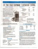


STAGE 1
SETPOINT
STAGE 2
SETPOINT
ON
=
ENERGIZED
OFF = DE-ENERGIZED
o
:
;;
"T1
m
:D
m
Z
-
<
O
N
~
o
Of
F
:
;
;
"
T1
m
~
S
TAGE
2
~
:
;;
r-
ON
(-)
F
i
gure 1
:
Two Stage Heating Example
STAGE 2
SETPOINT
w
a:
:>
t::
a:
w
Q
.
:::<
~
STAGE 1
SETPOINT
ON
=
ENERGIZED
OFF
=
DE-ENERGIZED
o
ON
:
;;
"
T1
m
:
D
m
~
~
STAGE
1
SETPOINT
STAGE 2
SETPOINT
ON
=
ENERG
I
ZE
D
OFF
=
DE-E
N
ER
G
I
Z
E
D
Programm
in
g
Steps and Displa
y
The E
T
C two stage ca
n b
e
p
r
og
r
a
m
m
e
d
i
n
se
v
e
n
s
i
mp
l
e st
e
p
s
u
s
i
ng the LCD
disp
l
a
y
and the t
h
r
e
e
e
y
s
e
f
a
c
e o
f
the c
on
tr
ol
.
pro
g
r
amm
i
ng
,
p
ress the
SET
key once to access
t
he
F
ahr
en
h
ei
t/
C
e
l
sius
mode
.
The display will show the cur
r
ent
s
tat
us
,
ei
t
her
F
for degrees Fahrenheit or C for degrees Cels
i
us.
Then press either the up
t
or down
.
arrow key to toggle
between the For C designation.
S
ta
ge
1
S
t
e
2
-
Press the SET key again to access the stage 1 setpoint
.
The
LCD will display the cur
r
ent setpoint and the S1 annunciator will
be blinking on and off to indicate that the control
i
s in the setpoint
mode. Then press eithe
r t
he up
t
key to increase or the down
•
key to decrease
t
he setpoint to the desi
r
ed temperatu
r
e
.
Press
t
he
SET k
ey again to access the stage 1 differe
n
ti
a
l
.
T
h
e
L
CD wi
l
l
display the current differential and the DIF 1
a
nn
unc
i
a
t
o
r w
i
ll
b
e
blinking on and off to indicate tha
t
t
h
e
co
nt
r
ol
i
s in th
e d
i
ff
e
r
ential
mode. Then press eithe
r
the
up
t
k
e
y
to
i
n
c
r
eas
e o
r
the down
•
key to decrease the differen
t
i
a
l
t
o
t
h
e
d
e
s
i
r
ed s
e
t
ting.
Press the SET key again t
o a
c
cess t
he stage 1 cooling or heating
mode. The LCD will d
i
s
p
l
a
y
t
h
e
c
u
r
r
ent mode
,
either
C1
for
cooling or H1 fo
r
h
e
a
ti
n
g.
Th
e
n
press e
i
ther the up
t
o
r
down
•
key to toggle be
t
w
e
e
n t
he C1
o
r
H1
designation.
Stage 2
Step
5
-
Press the
SET k
ey agai
n t
o access the stage 2 set po
i
nt
.
The LCD
will disp
l
ay t
h
e current setpoint and the S2 annunciato
r
will be
blinking on and off to indicate that the control is in the setpoin
t
mod
,
e
.
Then press either the up
t
key to increase or the down
•
key to decrease the setpoint to the desired temperature.
P
r
ess
th
e SET
k
e
y
aga
i
n
t
o
acce
ss
t
h
e s
t
age 2
diff
erentia
l
.
T
h
e
LC
D
will d
i
splay
t
he cur
r
e
n
t diffe
r
en
t
ial and
th
e
DIF 2
a
n
nunciator
w
ill be blinking on and off to indicate that the control is in the dif-
fe
r
e
n
tial mode
.
Then press either the up
t
key to increase or the
d
o
w
n
•
key to decrease the differential to the desired setting
.
Step 7-
P
r
es
s the SE
T
key again to access the stage 2 cooling or heat
i
ng
mode
.
The LCD will display the current mode
,
either
C2 f
or cool-
i
n
g o
r H
2
f
or heating
.
T
h
e
n
p
r
ess either the up
t
or down
.
key
t
o
t
o
g
g
l
e between the
C2
or
H2 d
esignation
.
Press the SET key
once more and programming is comp
l
e
t
e.
NOTE
:
T
h
e
E
T
C
wil
l
a
ut
o
m
a
t
i
ca
lly
e
n
d programming if no keys are
depress
e
d f
o
r
a pe
r
i
o
d
o
f th
i
rt
y
seconds
.
Any settings that have
been
inp
u
t t
o
t
he co
n
t
r
o
l w
il
l
be accep
t
ed at
t
hat point
.
All
cont
r
o
l
s
e
tt
in
gs
a
r
e e
t
a
in
e
d
i
n n
on
-
v
o
l
a
t
il
e
m
emo
r
y
i
f
p
ow
e
r t
o E
T
C
i
s
i
nterrupted
for a
n
y
r
eas
o
n
.
R
e
-
p
r
og
r
a
m
ming
i
s no
t n
eces
s
a
r
y
af
t
er power ou
t
a
ges o
r
d
i
sc
onn
e
cts
u
n
l
e
s
s d
i
f
fe
r
en
t
control settings
a
r
e requ
i
red
.