manualshive.com logo in svg
background image

LPY2 

 6  

LOGI LOW FREQUENCY MODIFICATION 

If your radio system requires DC isolation or you plan to use your Logi below 
900 MHz, the small connecting traces near the rear of the antenna should be 
cut. By removing these traces you can extend the effective frequency range 
down to 825 MHz. You will however 
wind up with some ‘lumps’ in the 
matching response on the high 
frequency end. 

BUILDING A CORNER REFLECTOR 

Corner reflector antennas have long 
been used by the Military and Radio 
Amateurs for high forward gain 
applications like field data links. Using a 
properly sized 90

°

 angle corner reflector 

will typically give you a 10 dB gain or 
higher over that of a stand alone dipole 
antenna. The construction of a traditional corner reflector is very simple. Two 
plates are connected at a 90

°

 angle with a feed element, usually a dipole, 

positioned along the vertex at the angular focal point of the plates. The 
dimensions of the reflector plates are luckily not critical (within reason of 
course) and the frequency characteristics are much better than most other 
parasitic arrays with the same gain rating. One drawback of the normal corner 
reflector arrangement is the fact that the active (radiating or receiving) element 
is usually a narrow bandwidth dipole. In our case, we suggest using the 
‘broadband’ Logi as the feed element. This gives you the same corner reflector 
benefits but without the normal narrow bandwidth limitations! 

With the wealth of information available today on the Internet, countless articles 
and design schemes can be found covering the construction of corner 
reflectors. The main difference from the norm is the use of the Logi as the main 
element versus a simple dipole. The following diagram gives a few basic 
dimensions for an experimental corner 
reflector. The main points to key in on are 
the base reflector size and the element (the 
Logi) placement for proper broadband 
coverage. 

Different types of materials can be used to 
form the reflector plates. Any type of 
perforated aluminum or copper sheet will 
work well. Small holes in the material help 
to cut down on wind resistance. The overall 
reflector length and width sizes should be 
chosen to properly work at the lowest 

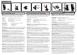
Soldered Coax Positioning 

Final Installation View 

Содержание LPY2

Страница 1: ...signal into a powerful beam that is 4 times more powerful in the direction you desire Easy hookup to your Receiver or Transmitter Small thin size with excellent broadband performance Solid 6 dB gain f...

Страница 2: ...LC1 Inductance Capacitance Meter RAMSEY AMATEUR RADIO KITS DDF1 Doppler Direction Finder HR Series HF All Mode Receivers QRP Series HF CW Transmitters CW7 CW Keyer CPO3 Code Practice Oscillator QRP P...

Страница 3: ...y Modification 7 Building a Corner Reflector 7 Building a Reflector Grid 9 LPY2 Return Loss Plot 10 Return Loss vs VSWR Chart 10 Warranty 11 KIT ASSEMBLY AND INSTRUCTION MANUAL FOR RAMSEY ELECTRONICS...

Страница 4: ...put impedances and good VSWR characteristics While the log periodic design has been around since the late 1950 s it has now been discovered to be at the cutting edge of antenna development Looking at...

Страница 5: ...al cable such as RG 142 141 and 085 semi rigid will also provide you with a good low loss connection as well as excellent high frequency characteristics Let s take a look at the circuit board for a mo...

Страница 6: ...s are much better than most other parasitic arrays with the same gain rating One drawback of the normal corner reflector arrangement is the fact that the active radiating or receiving element is usual...

Страница 7: ...rror to get things just right Use a piece of PVC pipe 1 2 to 7 8 will work well with a slot cut in the end just big enough to wedge the entire Logi in place The narrow front edge of the circuit board...

Страница 8: ...1 2 to 1 PVC coupler non threaded 1 3 4 to 1 PVC coupler threaded on the male 3 4 side only 1 can of PVC cement 3 4 minimum nylon wire ties 10 0 12 0 Cut a slot into the PVC boom Insert the Logi narro...

Страница 9: ...LPY2 9 LPY2 mounting Boom for a Grid Reflector LPY2 mounted on a Grid Reflector...

Страница 10: ...0 1 377 30 0 1 065 7 0 2 615 17 0 1 329 35 0 1 036 8 0 2 323 18 0 1 288 40 0 1 020 9 0 2 100 19 0 1 253 50 0 1 006 10 0 1 925 20 0 1 222 60 0 1 002 RETURN LOSS VERSUS VSWR CONVERSION CHART The LPY2 of...

Страница 11: ...be assured that the 1K ohm resistors are actually the missing 10 K parts Hum m m I guess the red band really does look orange Ramsey Electronics project kits are packed with pride in the USA If you b...

Страница 12: ...amsey RTS05 Small Diagonal Cutters Ramsey RTS04 OR Complete Soldering Tool Set RS64 2801 ADDITIONAL SUGGESTED ITEMS Optivisor Magnifier Headband Ramsey OPMAG Holder for PC Board Parts Ramsey RTS13 Des...

Отзывы: