


7
RAK5205 User Manual V1.4
RAK
5205
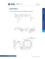
2.2
Functional Diagram
The block diagram below shows internal architecture and external interfaces:
Image 4
| Functional Diagram
2.3
Interfaces
It is built around RAK811 module and compatible with 96Boards. It provides the
following interfaces, headers, jumpers, button and connectors:
Micro USB
30-pin 96Boards Headers (UART, RESET, GPIOS, I2C, ADC)
2-pin USB Boot jumper
3-pin UART RX jumper
2-pin Battery female interface
2-pin Solar Panel female interface
LEDs
Reset Button
It has two Antenna connectors:
RP-SMA Male connector of LoRa Antenna(optional iPEX connector)
SMA Female connector of GPS Antenna(optional iPEX connector)
R
A
K
52
05
Fu
nc
tio
na
lD
ia
gr
am