background image


58


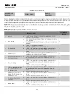
k. 

Starter Lock 


Inspect for damage due to corrosion, lack of maintenance, or 

abuse. 


Lubricate with Friction Surface Marine Grease. 

k.   

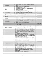
l. 

Battery 


Inspect battery case for damage. 


Inspect cables for cracks, chaffing and insulation damage. 


Check battery mounting. 


Inspect battery connector for corrosion. 


Lubricate battery connector with dielectric grease. 

l. 


m. 

Electrical Wiring 


Inspect wires for cracks, chaffing and insulation damage. 


Check for loose connections. 

m.   

n. 

Ignition Coil Plug Wire 

Boots 


Prior to submersion, remove plug boots and fill with dielectric 

grease. 

n.   

o. 

Gearcase 


Inspect water intake screens 


Inspect Skeg for damage 

o.   

p. 

Propeller 


Inspect and verify propeller is true and free of nicks, chips, and 

other damage that could affect performance. 

p.   

q. 

Propeller Shaft 


Inspect for damage due to corrosion, lack of maintenance, or 

abuse.


Inspect the shaft threads and splines for wear and 

damage. 


Lubricate with Friction Surface Marine Grease. 

q.   

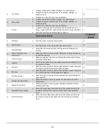
Fuel System


Completed 

(initial) 

a. 

Gasoline Fuel Mix Ratio  


Requires a 40:1 oil to fuel mixture. 16oz per six (6) gallons or 

about 2.5oz per every one (1) gallon. 


Use only NMMA TC-W3 2-Cycle motor Oil. 


Record date of mix, dispose of fuel mixtures older than 90 days. 

a.   

b. 

Heavy Fuel Mix Ratio 


Requires a 12:1 Raider Elixir mixture. One (1) can Raider Additive 

per six (6) gallon of fuel. 64oz per six (6) gallons or about 10.5oz 

per every one (1) gallon of fuel in addition to the 40:1 oil to fuel 

mixture. 


Use only NMMA TC-W3 2-Cycle motor Oil. 


Record date of mix, dispose of fuel mixtures older than 90 days 

b.   

c. 

Fuel Bladder/Tank 


Inspect for leaks: Ensure that the bladder is not leaking from any 

seam, fill cap, vent, or rip in membrane. 


Inspect securing straps: Ensure the bladder can be adequately 

secured to the deck. 


Inspect fuel line connector: Check for damage and ensure that 

the fuel line fitting properly mates. 


Inspect vent: Ensure the vent opens and shuts. 

c.   

d. 

Fuel Line Assembly 


Inspect end connectors: Check ensuring proper fit and seal to 

bladder and Raider. 


Inspect fuel line: Check for dry rot and leaks. 


Inspect bulb: Check for proper installation, dry rot, and function. 


Stow extra Fuel Line Assembly in sponson bag or Emergency Kit. 

d.   

e. 

Heavy Fuel Block Valve 


Ensure that the Heavy Fuel Block Selector Valve is lock wired in 

the shut position when using gasoline. 

e.   

f. 

Fuel Filter 


Inspect component for leaks, damage, or excessive wear.  


Inspect Clamps: Ensuring proper fit, note leaks, damage, or 

excessive wear.  


Inspect Lines: Check for dry rot and chaffing.  

f. 


Содержание Raider 40 HP

Страница 1: ...i ...

Страница 2: ...ii This page intentionally left blank ...

Страница 3: ...dy Space Center located in the Space Port Commerce Park We design and produce multi fuel submersible lightweight outboard motors and associated parts that include a Safety Jet transom plates carts and transportation cages Our markets include Department of Defense DOD Other Government Agencies OGA National and Local Law Enforcements and First Responder Services Search Rescue and commercial retail T...

Страница 4: ...able Bagless submersion Superior dewatering Leader in horsepower to weight ratio 25 better fuel efficiency than any other motor in its class Easy to maintain and troubleshoot OUR MISSION Raider Outboards will provide and deliver the most reliable premium products hands on training and highest quality to the customer and serve as the premier outboard motor company to the U S Military while honoring...

Страница 5: ...es described later are followed carefully Should difficulty arise with the motor please follow the troubleshooting procedures listed throughout the specified sections within this manual For any other issues questions or concerns please call 321 567 2306 or contact TechSupport raideroutboards com where our trained staff of subject matter experts will provide you with any assistance required OWNER R...

Страница 6: ...e caused by failure to adhere to the dewatering procedures 5 Damage from accidents collisions contact with foreign materials or submersion without cleaning 6 Growth of marine organisms on motor surfaces that exceeds recommended submergibility times or left in the water between operational periods 7 Any other careless use or operation issues Battery unplugged when not in use 8 Normal deterioration ...

Страница 7: ...b site raideroutboards com and may be downloaded for convenience Should additional information be required please call or email customer service department at 321 567 2306 or TechSupport raideroutboards com b For our users we have built the best outboard motor for long term it is essential for the maintainer to prepare the outboard prior to the operational period To ensure this the maintenance and...

Страница 8: ...erial Requirements 20 Break In 21 STANDARD OPERATING PROCEDURES 22 Pre and Post Operations Checks 22 Pre Operations Checks 23 Operational Checks 26 Post Operations Checks 28 Motor Mounting 29 Propeller Selection 30 Starting the Raider 40 HP 31 Maneuvering 34 Trim Adjustments 35 Shallow Water Running Beaching 37 Dewatering 38 Emergency Tertiary Starting 41 MAINTENANCE REQUIREMENTS 42 Tach Hour Mete...

Страница 9: ...ix Gear Oil Change 51 Gearcase Pressure and Vacuum Tests 53 TROUBLESHOOTING 54 APPENDICES 56 Pre Operations Checklist 57 Post Operations Checklist 61 ...

Страница 10: ...r otherwise handling your Raider Outboard Motor be sure to thoroughly read and understand this operations section of this manual and carefully follow all of the instructions Of particular importance is information preceded by the words DANGER WARNING CAUTION and Note Always pay special attention to such information to ensure safe operation of the outboard motor at all times The following safety st...

Страница 11: ...rs and Field Service Technicians with the necessary tools to perform routine maintenance actions or intermediate level motor troubleshooting and repair to the component level The tools are stowed and secured in a waterproof case for ease of transport and protection from harsh environmental conditions For inquiries into purchase of the RMK please contact Raider at sales raideroutboards com or 321 5...

Страница 12: ...arried onboard the craft as part of the operational load out This kit is not inclusive and additional items may be required based on organizational Standard Operating Procedures SOP The EFK includes the following items Part Number Qty Description SBE110 2 Spark Plug 841140 1 M10 Deep Socket 3 8 Dr 841156 1 M16 Deep Socket 3 8 Dr 841153 1 M13 Deep Socket 3 8 Dr 2292340 1 Stanley 6 way screwdriver 6...

Страница 13: ...s few as 30 seconds Air Deployable When required is capable of being dropped from both fixed wing and rotary aircraft Battery cutoffs are available to preserve start battery life in drop packages for over 180 days Prior to drop the operator enables the start battery should expeditious start be required on the drop zone Lightweight Maneuverable through the hatch of a Submarine or mounting when unde...

Страница 14: ...ormance of maintenance actions and repairs For safe secure storage the cart maybe locked into place inside the Transportation Cage This provides extra protection when conducting movement via land or by Military Air ensuring your motor arrives in theater ready for immediate operations Engine Cover Protects motor from prevailing environmental conditions should the need require stowage in less than i...

Страница 15: ...on system Fuels pre mixed with additives Cooling system Forced Water cooling Water temperature control Thermostat with pressure relief valve Ignition System Flywheel Magneto C D Ignition Gear Reduction Gear Ratio 13 25 1 85 Spark Plug NBE1H 10 stainless steel GAP 035 Alternator 12V 280W Maximum 13 6 volts regulated Battery Acid Glass Mat AGM 12VDC 10Ah with 175CCA Trim Angle 4 24 degrees Trim Angl...

Страница 16: ...wer 4 Water Check Port 14 Dewatering Lever 24 Emergency Stop Switch 5 Rear Carry Grab Rail 15 Throttle Grip 25 Front Grab Handle 6 Fuel Overboard Tube 16 Throttle Tension Adjust 26 Stern Bracket Anode 7 Water Plug 17 Shift Lever 27 Primer 8 Reverse Lock Lever 18 Stern Bracket Clamp 28 Electric Start 9 Drive Shaft Housing 19 Stern Bracket 29 Fuel Connect 10 Anti Ventilation Plate 20 Thrust Rod ...

Страница 17: ...the powerhead and components during operation and storage Cowling Latch A mechanism located on the rear portion of the lower engine cover that provides a means to secure the cowling in place Cowling Retention Strap Velcro Straps fixed to the cowling and lower engine cover that prevent the cowling from dislodging during air drop motor submersion or craft capsize ...

Страница 18: ...sed to start the motor Tiller Arm Mechanical lever the attaches to the swivel bracket that allow the operator to steer the craft to port or starboard Also provided the mounting structure for the Throttle Control and Throttle Tension Adjustment Throttle Control Affixed to the end of the Till Arm Allow the operator to control the acceleration and deceleration of the motor It provides a raised indica...

Страница 19: ...to operator preference Forward Carry Grab Handle Located on the forward part of the motor Provides the operator with a secure means to lift the motor for movement or mounting Carry Grab Rail Located around the left right and rear of the motor Provides a means for the operator to lift the motor for movement or mounting Also provides a means for the motor to me laid down in the upright position Coat...

Страница 20: ... expelled from the cylinders Features a detent position to allow for hands free operation while dewatering Gear Shifter Located on the forward section of the lower engine cover Three position lever that allows for selection of forward neutral and reverse Ensure that the throttle is at idle before placing the motor into gear Tachometer Hour Meter Displays the total number hours the Raider Outboard ...

Страница 21: ...n Switch Push button start switch that utilizes battery voltage to activate an electric starter to spin the flywheel Electric start is protected by an outer ring to prevent inadvertent activation from contact This is the secondary method to start the motor Located on the front of the lower engine cover Engine Stop Push Button Kill Switch Located on the front of the lower engine cover Push button s...

Страница 22: ...ure place on the operators clothing When the lock plate is removed the motor will stop Primer Located on the front of the lower engine cover Utilized for cold starts and dewatering When actuated pumps fuel from the carburetor bowl to the Heavy Fuel Plate to aid in starting Fuel Overboard Discharge Drain Tube The through put for the fuel system that provides passage for bad fuel from the fuel syste...

Страница 23: ... Handle A two position lever when in the fully down position will release the motor to be place into the Shallow Running Position or full tilt When in the up position locks the motor in the down position Located on the right side of the Swivel Bracket Tension Adjustment Bolt Located Utilized to adjust the tension when moving the motor to the left or right and centering by turning the bolt clock wi...

Страница 24: ... Bracket Anode Made of zinc a highly active metal that attracts electrolytes that would normally corrode and weaken the less active metal Oil Level Plug Located just Beneath the AV Plate on the forward portion of the Gearcase When open it release vacuum in the Gearcase to allow oil to drain freely from the Lower Fill Drain hole When filling provided indication that Gearcase is full when oil seeps ...

Страница 25: ...aust Outlet The exhaust relief is located above the AV plate allowing the prop to run in clean exhaust free water Water Strainer Set Located on both sides of the Gearcase A fabricated beveled opening covered by a plastic screen that allows for the intake of water by the impeller for cooling This is simply a small plastic basket that is tapered and has perforation holes which acts as a filter for l...

Страница 26: ...im Tab A fin shaped object attached behind the propeller that serves two functions Functions as a zinc anode and counter acts the torque pressure generated by the propeller spin that makes steering more difficult Skeg The lowest point on an outboard motor improves directional stability Protects the prop from impact The angle of the skeg deflects the Gearcase from rocks and logs ...

Страница 27: ...ed Regardless of what fuel is utilized the fuel must be mixed with a certified NMMA TC W3 2 Cycle motor Oil Raider Outboards provides a specially formulated TC W3 developed by VP Racing The Raider Outboards TC W3 2 Cycle Outboard Synthetic Marine Oil is specifically designed to meet the lubrication requirements of a submersible engine Use of low quality gasoline results in a short engine life as w...

Страница 28: ...sal instruction for your organization The only lubrication provided for the Raider Outboard Motor is through the oil added to the gasoline therefor running with too little oil will cause engine damage Oil burns differently than gasoline however and running too much oil will make the engine run poorly smoke excessively foul spark plugs and will even plug up the exhaust with oil residue So it is vit...

Страница 29: ...ol Cleaning Solvent Dielectric grease Marine Lithium Grease Loctite 243 Threadlocker Battery Spray Protector Permatex thread locking compound Loctite 272 Permatex High tack gasket sealant Loctite 242 Threadlocker Lower Unit Gear Oil API Grade GL 5 SAE 80W 90W TC W3 2 Cycle Outboard Synthetic Marine Oi Silicone Spray Anaerobic gasket maker anti seize ...

Страница 30: ... 3 10hrs After 10hrs Throttle Position Idle Less than 1 2 throttle Less than 3 4 throttle 3 4 throttle Full throttle available Speed Approx 3000 rpm max Full throttle run allowed for 1 min every 10 min Approx 4000 rpm Full throttle run allowed for 2 min every 10 min Operating the outboard motor without break in can shorten service life of the product If any abnormality is experienced during the br...

Страница 31: ...he motor during an operational cycle or mission Post Operations Checks are developed and implemented for the purpose of establishing a maintenance procedure to be conducted after each operational cycle or mission that mitigates operational stressors placed on the motor while in use extends service life of the motor and improves reliability of the motor Formal documentation provided by Raider Outbo...

Страница 32: ...and Shift Lever Stopper Inspect for damage due to corrosion lack of maintenance or abuse Loose ball joints locknuts bent link rods loose rod snaps Throttle Linkage Inspect for damage due to corrosion lack of maintenance or abuse Loose ball joints locknuts bent link rods loose rod snaps Lubricate with low temperature lithium grease Tilt Stopper Bracket Bolt Bracket Shaft Clamp Screw and Reverse Loc...

Страница 33: ...r every one 1 gallon Use only NMMA TC W3 2 Cycle motor Oil Record date of mix dispose of fuel mixtures older than 90 days Lubricate with Friction Surface Marine Grease Heavy Fuel Mix Ratio Requires a 12 1 Raider Elixir mixture One 1 can Raider Additive per six 6 gallon of fuel 64oz per six 6 gallons or about 10 5oz per every one 1 gallon of fuel in addition to the 40 1 oil to fuel mixture Use only...

Страница 34: ... dry rot and chaffing Fuel Pump Inspect component for leaks damage or excessive wear Inspect Clamps Ensuring proper fit note leaks damage or excessive wear Inspect Lines Check for dry rot and chaffing Carburetors Inspect component for leaks damage or excessive wear Inspect Clamps Ensuring proper fit note leaks damage or excessive wear Inspect Lines Check for dry rot and chaffing Primer Inspect for...

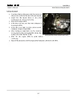
Страница 35: ...es not engage when the gear selector is in the neutral position Forward With the motor at idle verify the Gear Selector moves freely into the forward position and the propeller engages Reverse With the motor at idle verify the Gear Selector moves freely into the reverse position and the propeller engages Throttle Control With the engine in neutral slowly increase the throttle RPM s to approximatel...

Страница 36: ...HP SECTION 2 Owner s Manual Standard Operating Procedures 27 Full Tilt Position Move the motor Reverse Lock Lever to the release position lift the Lower Unit past a 90 angle until the tilt stopper assembly locks ...

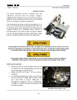
Страница 37: ...ter a submersion period the motor must be run at operating temperature for no less than 30 minutes to ensure all water is removed from the head Disconnect the fuel supply and let the motor run itself dry Wipe Down Use LP air or dry cloth to remove excess water from exterior and interior surfaces of the motor After submersion use LP air to remove water and moisture under the Flywheel and Recoil Sta...

Страница 38: ... the water surface when running with wide open throttle If the water is being pushed into the craft raise the motor on the transom by adding a shim on top of transom to achieve proper motor height Attaching the Stern Bracket Both Zodiac and Wing inflatables should come with a transom plate attached These plates provide a guide for the stern bracket of the motor that will automatically center the R...

Страница 39: ...15 pitch propeller would move forward 15 inches in one revolution The lower the prop pitch the better your hole shot However this comes at a price top speed The lower pitch makes the engine reach maximum rpm at slower speeds Conversely a higher pitch will deliver greater top speeds but slower acceleration If you re changing pitch remember that each inch of pitch is worth about 200 rpm Lowering the...

Страница 40: ...gages the starter motor to start the engine This method of starting is normally used when under duress or prevailing conditions prevent motor start by the primary method The tertiary means to start the motor is used only when the primary and secondary have failed The engine cowling is removed to gain access to the Recoil Starter Using tools provided in the Emergency Tool Kit the recoil starter is ...

Страница 41: ... bulb until firm 5 Pump the Primer Valve two or thee times 6 Set the shift lever to Neutral 7 Turn the throttle grip so that the indicator line meets the START mark 8 Pull the starter rope slowly until resistance is met Give it a sharp tug to start the engine Electric start button can be used to start engine if user desires ...

Страница 42: ...age will result Be careful that your clothes or other items do not get caught in the rotating engine parts To prevent accident and injury do not reattach the recoil starter after the engine has been started using the emergency starter rope Be sure to put the top cowl back on Do not operate the outboard motor with top cowl removed from the power unit or contacting turning flywheel which can lead to...

Страница 43: ... the gear shift lever in the neutral position Secure craft to pier if required Press the engine stop switch Reversing Turn the throttle grip toward SLOW and move the Shift Lever quickly to Reverse when the engine speed has reached the lowest RPM Ensure the Tilt Lever is in the locked position fully up If not when engaged the propeller will climb out of the water Ensure that the Lock Plate Lanyard ...

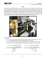
Страница 44: ...craft to the water accordingly Trimming Out Excessively bow rises too high If the trim angle is set to far out the bow will rise out of the water and the speed will decrease Furthermore the bow may sway or the bottom may slam the water while cruising In this case decrease the trim angle by setting the thrust rod in a lower hole Trimming In Excessively bow sinks or broaches If the trim angle is set...

Страница 45: ...trolled safely Do not put hand or finger in between outboard motor body and clamp bracket when adjusting trim angle to prevent injury in case the outboard motor body falls Unsuitable trim position can cause loss of control of boat Do not cruise at high speed if improper trim position is suspected Stop the boat and readjust trim angle before continuing cruise For outboard motor model with PTT switc...

Страница 46: ...d fail When operating reverse propulsion do not accelerate rapidly Rapid acceleration will cause the propeller to climb out of the water and may dislodge from the transom or injure personnel During shallow water operation be careful not to place your hand between the swivel bracket and the stern bracket Be sure to tilt the outboard down slowly Run at lowest possible speed during cruising using sha...

Страница 47: ...ake sure the inside of all electrical connectors are coated with dielectric grease and firmly connected Ensure the Dewatering Lever is locked forward shut Ensure battery is fully charged and re connected correctly Ensure fuel bladder if fully filled with 40 1 oil mix and cap tightened Connect fuel line and pump primer bulb until firm resistance is felt to fill fuel system Dewatering Procedure Secu...

Страница 48: ...ommends that your organization use STA BIL 360 Marine treated fuel during this run period STA BIL 360 Marine provides enhanced water removal properties to prevent fuel system corrosion Engineered specially for the harsh coastal climates prevents corrosion cleans the fuel system and prevents the buildup of unwanted gum and varnish mitigating the adverse effects of submerging your Raider 40 HP After...

Страница 49: ...TION 2 Owner s Manual Standard Operating Procedures 40 Leave the upper cover off when possible to allow the power head and other components to air dry Unplug or remove battery place on battery tender to maintain charge ...

Страница 50: ...and one 1 13mm bolt washer that secure the recoil starter over the starter pully and flywheel Remove the retention clip from the Neutral Safety Starter Lock and stow the Recoil Starter Using the cord from the ETK tie a knot in one end Wind the cord around the flywheel and use a socket Use a socket wrench or similar to get a firm grip on the end of the rope Give it a sharp tug to start the engine B...

Страница 51: ...ion connectors Heavy Fuel Block lock wire material condition connectors Primer material condition Dongle material condition connectors Ignition Spark Plugs clean inspect gap check Ignition Coils clean inspect grease Starting System Starter Rope material condition Starter Motor disassembly cleaning and inspection Engine Compression Test 155 psi 10 Flywheel clean inspect Coil Plate clean inspect Dew...

Страница 52: ...w seconds Timing System TOT Accumulates motor total hours non resettable JOB Records partial motor operating time resettable SVC May be set between 5 and 50 Hours countdown based on user requirements or service intervals When time is reduced to zero 0 0 SVC will flash indicating required service action Default setting is 5 hours SVC2 May be set between 10 and 250 Hours countdown based on user requ...

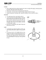
Страница 53: ...he Boot Extensions replace cracked arc tracked or otherwise damaged Visually inspect the boot and ignition contact for evidence of arcing or other damage Remove each spark plug with a 16mm deep well socket Carefully seat the wrench securely on the plug to avoid damage to the threads or barrel Inspection Visually inspect Dispose of plugs with worn damaged or cracked Terminal Ends Insulators threads...

Страница 54: ...gap tool into the space between the spark plug s body and the electrode that sticks out of it Use the tool to measure the gap then either pry the electrode further from the body to increase the gap or press it closer to the body to decrease it until the gap matches Gap Tool is included with the Raider Outboards Maintenance Tool Kit Install Install spark plug fully hand tighten and then use 16mm de...

Страница 55: ...rew Reset Slowly turn the set screw clockwise Stop as soon as resistance is met Tightening the set screw will result in damage to the carburetor Slowly turn the set screw 1 turns counter clockwise The Idle Speed Adjustment Screw is set from the factory so that the engine idles between 1 000 and 1 100 RPM in neutral Differences in atmospheric conditions such as temperature humidity or altitude will...

Страница 56: ...Observe the engine RPM If the idle is too low turn the screw clockwise to raise engine RPM If the idle is too high turn the screw counter clockwise to lower engine RPM After making an adjustment rev the motor by turning the throttle until engine RPM climbs then quickly return the throttle to idle Wait for the engine RPM to settle before continuing Repeat this procedure until the engine idles betwe...

Страница 57: ...ere the seam fitting line of the crank case and block coincide To make adjustments remove the Ball Joint Connector from the Coil Plate Adjust the length of the Advancer Link Rod so that the ignition timing match mark lines up with the fitting line of the crankcase and block and lock it with a nut Timing Settings B T D C Turn the throttle grip to the fully open position Verify the timing match mark...

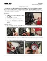
Страница 58: ...e operational cycle for depot level service Preparation Bring the motor up to operating temperature and secure Disconnect the fuel source Remove the lock plate lanyard and stow Remove the spark plug from the cylinder to be test IAW the procedures contained in this section Performing the Test Attach the compression test adapter into the cylinder to be tested and connect the compression gauge to the...

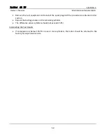
Страница 59: ...k plug IAW the procedures contained in this section Repeat the testing process on the remaining cylinder The difference across cylinders should not exceed 15 PSI Interpreting the Test Results If compression is below 155 PSI in one or more cylinders the motor should be returned to the factory for depot level service ...

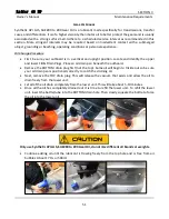
Страница 60: ...ower Fill Drain Plugs Place an oil drain pan beneath the outboard Remove the BOTTOM drain plug first not the top Some oil will begin to trickle out so be sure your oil drain pan is positioned correctly to catch the draining oil Next remove the TOP drain plug This will release the vacuum that exists and allow the oil to drain freely from the lower unit Let all of the oil drain completely from the l...

Страница 61: ...l is going bad or the O rings for either the fill or drain plug Metal shavings The presence of small sand like shavings are common and consistent with normal wear Should larger pieces or chunks with a grey oil color be observed indicates a more significant problem Consider a lower unit swap or depot level service Check Oil Level Remove the top oil plug insert a small piece of wire straight into th...

Страница 62: ...tall the gearcase pressure tester into the Oil Level Plug fitting Pump the pressure tester until the gauge indicates 3 6 PSI Gearcase should maintain pressure for 2 minutes If pressure loss occurs determine source by submerging gearcase in water Once source is identified make necessary repairs to correct the problem and retest Remove the pressure tester and install the gearcase vacuum tester pump ...

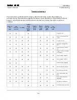
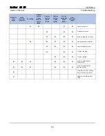
Страница 63: ...oor Idling Unstable engine running speed or engine speed Abnorm ally high engine speed Abnorm ally low engine speeds Cannot obtain high engine speeds Over heating of engine Empty fuel tank Incorrect connection of fuel system Air enters fuel line Deformed or damaged fuel pipe Closed air vent on fuel tank cap Clogged fuel filter fuel pump or carburetor Use of improper engine Oil Use of improper Gaso...

Страница 64: ...orm ally low engine speeds Cannot obtain high engine speeds Over heating of engine Faulty thermostat Propeller cavitation Incorrect propeller selection Damaged or bent propeller Unbalanced load in boat Transom too high Transom too low Incorrect adjustment of throttle link Incorrect adjustment of ignition timing Insufficient battery capacity loose terminals corrosion Safety switch lock plate not fi...

Страница 65: ...56 APPENDICES ...

Страница 66: ...rrosion lack of maintenance or abuse Loose ball joints locknuts bent link rods loose rod snaps c d Cable Lanyard Verify the Cable Lanyard is securely attached to the motor and maybe securely attached to craft Transom d e Shift Lever Mechanism and Shift Lever Stopper Inspect for damage due to corrosion lack of maintenance or abuse Loose ball joints locknuts bent link rods loose rod snaps e f Thrott...

Страница 67: ...rd date of mix dispose of fuel mixtures older than 90 days a b Heavy Fuel Mix Ratio Requires a 12 1 Raider Elixir mixture One 1 can Raider Additive per six 6 gallon of fuel 64oz per six 6 gallons or about 10 5oz per every one 1 gallon of fuel in addition to the 40 1 oil to fuel mixture Use only NMMA TC W3 2 Cycle motor Oil Record date of mix dispose of fuel mixtures older than 90 days b c Fuel Bla...

Страница 68: ...ischarged from all check ports d e Tiller Steering When moving the Tiller Arm verify that the motor moves freely to port and starboard e f Neutral Verify the propeller does not engage when the gear selector is in the neutral position f g Forward With the motor at idle verify the Gear Selector moves freely into the forward position and the propeller engages g h Reverse With the motor at idle verify...

Страница 69: ...60 Notes and Discrepancies ...

Страница 70: ...r flush Attach ears or flush connector to lower unit Operate the engine for approximately five 5 minutes at full operating temperature After submersion period the motor must be run at operating temperature for no less than 30 minutes to ensure all water is removed from the head Disconnect the fuel supply and let the motor run itself dry b c Wipe down Use LP air or dry cloth to remove excess water ...

Страница 71: ...Raider 40 HP Appendix Bravo Owner s Manual Pre and Post Operations Check Sheet 62 Notes and Discrepancies ...

Страница 72: ...This page intentionally left blank ...

Страница 73: ......

Отзывы: