889-3809-02
Model 2018E Operations Manual Rev Apr 2020 Page
30
of 39
4.1
PRINTED CIRCUIT BOARD SWITCHES & JUMPERS
4.1.1
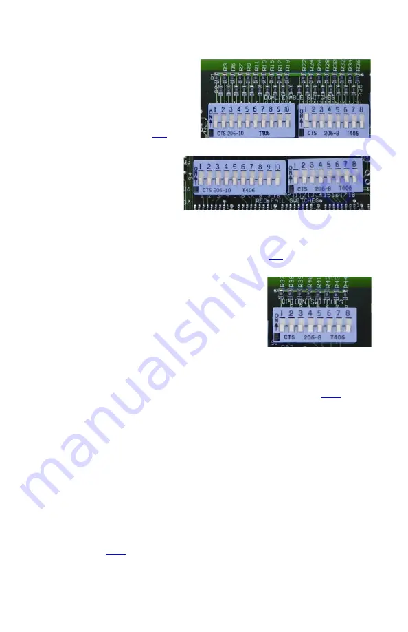
DUAL INDICATION ENABLE SWITCHES
Eighteen DIP switches on the PC board enable, on a
per channel basis, Dual Indication monitoring. The
switches, labeled DUAL ENABLE SWITCHES, are
located near the upper left corner of the PC board.
The numbers 1 through 18 correspond to the monitor
channel that the switch affects. When a switch is
ON, Dual Indication monitoring will occur for that
channel. The factory default for the channel settings
of this option is all channels disabled. For details on
Dual Indication monitoring see Section
4.1.2
RED FAIL SWITCHES
Eighteen DIP switches on the PC board enable,
on a per channel basis, Red Fail monitoring.
The switches, labeled RED FAIL SWITCHES,
are located near the upper right corner of the PC
board. The numbers 1 through 18 correspond
to the monitor channel that the switch affects.
When a switch is ON, the monitor will only
perform Red Fail monitoring for that channel when the Red Enable input is active. The factory default for the
channel settings of this option is all channels enabled.
Only the Red Fail monitoring is affected by this feature. Other monitoring normally controlled by the Red Enable
input (Short Yellow, Short Clearance, and Dual Indication) still operate as defined and are not affected in any way
by the activation of this feature. For details on Red Fail monitoring see Section
4.1.3
OPTION SWITCHES
Eight DIP switches on the PC board enable one or more of eight user
selectable options. The switches, labeled OPTION SWITCHES, are located
near the upper right corner of the PC board. The numbers 1 through 8
correspond to the option that the switch enables. When a switch is ON, then
the option is enabled.
4.1.3.1
SWITCH 1 – FLASHING DON’T WALK
MONITORING (DW MON)
When ON, the monitor will ensure that flashing Don’t Walk displays to not
conflict with other greens or yellows at the intersection. In order to use this feature the RaeComM software must
be used to set the channels that this feature is enabled for. The factory default for this feature is no channels
enabled.
When a fault is detected due to this feature, it is displayed as a CONFLICT and the channel with a flashing RED
input that was involved in the detected fault will be flashing its RED LED. See Section
information.
To view the channels that will have flashing Don’t Walk monitoring enabled, perform the following steps:
1.
Press and hold the front panel
RESET
switch until 1 beep is heard to activate Diagnostic Display.
2.
Tap the
RESET
switch two times to get to the C2 (Configuration Screen 2) display.
3.
Red channel LEDs will display an ON for channels with this feature enabled.
4.
Press and hold the front panel
RESET
switch until 1 beep is heard to return to normal operation.
NOTE: The monitor will continue to operate normally while in the diagnostic display mode. Any fault detected
while in this mode will be displayed correctly when returned to normal operation.
4.1.3.2
SWITCH 2 – FLASHING YELLOW ARROW ENABLE (FYA EN)
When ON, the monitor will activate special internal logic to properly monitor a Flashing Yellow Arrow
Protected/Permissive Left Turn. Refer to Application Note AN-005 for detailed examples of Flashing Yellow
Arrow implementations.
The channel that will display the solid Red arrow, Yellow arrow, and Green arrow is the parent channel. It is
necessary to define the conflicting through and the channel where the flashing Yellow arrow itself will be
connected. See Section
for more information.
To view the Flashing Yellow Arrow settings for each channel perform the following steps:
1.
Press and hold the front panel
RESET
switch until 1 beep is heard to activate the Diagnostic Display.
2.
Tap the
RESET
switch two times to get to the C2 (Configuration Screen 2) display.
3.
Press and hold the front panel
RESET
switch until 2 beeps are heard to activate FYA sub menu display.


