2 SCOPIA
100
MCU Quick Start
Using the MCU
14.
Note
For more detailed information, see the SCOPIA
100
MCU
User Guide
I
NTRODUCTION
The SCOPIA
100
MCU unit contains two components for
performing audio and videoconferencing—the MCU and the
SCOPIA Media and Video Processor (MVP). The MCU (the
upper component) is responsible for signaling and audio. The
MVP (the lower component) is responsible for video. The MCU
and MVP components connect via the Ethernet.
For correct operation, the MVP card must register with the MCU.
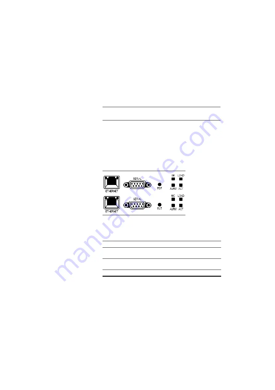
Figure 1
SCOPIA
100
MCU Front Panel
C
OMPONENT
D
ESCRIPTION
ETHERNET connector
An RJ-45 connector that provides the primary
Ethernet connection for the IP network port.
SERIAL connector
A DB-9 connector that allows you to connect
a PC terminal for local configuration.
RST button
Allows you to reset the MCU/MVP manually.


