background image

11 


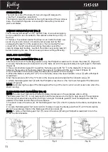
STORAGE (FIG. 6) 

The right rear side of the body (1) has a storage (2) designed to 

  store the T-shaped hex wrench (3). 

The blade storage (4) is located on the right rear side of the scroll saw 

body. The blade storage can conveniently store extra pin-end and 

plain-end blades.


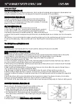
SAWDUST EXTRACTION PORT (FIG. 7) 

This scroll saw will accept a 1-1/4” (32mm) hose or vacuum accessory 

(not provided) to be connected to the sawdust extraction port (1) on 

the front 

of the base. If excessive sawdust buildup occurs inside the base, use 


a wet/ dry vacuum cleaner or manually remove sawdust by first 

unplugging the saw from the power source, then removing the two 

screws (2) on the left side of saw holding the plate cover. After 

cleaning all sawdust buildup, re-attach the plate cover and screws (2) 

before restarting the saw. This will keep your saw cutting efficiently. 


BEVEL STOP ADJUSTMENT 


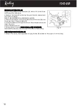
90 ° (0 °) BEVEL ADJUSTMENT (FIG. 8, 9) 

1. Remove the foot of the blade guard (2) using the Phillips®  screwdriver to loosen the screw (1). (Figure 8) 

2. Loosen the table lock knob (3) and move the table (4) until it is approximately at a right angle to the blade. 

(Figure 9)


3. Use a combination square (6) to position the table exactly 90 ° (0 °) to the blade (5). If there is space 

between the square and the blade, adjust the angle of the table until the gap is closed. (Figure 9) 

4. Lock the table lock knob (3) under the table (4) to prevent it from moving. 

5. When the blade is exactly 90 ° (0 °) from the table, loosen the bevel indicator screw (7) with a Phillips®  

screwdriver. 

6. Set the bevel scale (8) to the “0” mark on the bevel scale and retighten the indicator screw (7). 

7. Attach the blade guard foot (2) with the Phillips®  screwdriver so the foot rests flat against the table and 

tighten. (Figure 8) 

NOTE: Avoid placing the edge of the table against the top of the motor, which could cause noise when the 

saw is running. 


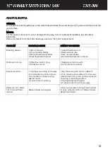
BLADE GUARD FOOT ADJUSTMENT (FIG. 10) 

NOTE: The user must maintain a constant downward pressure on the workpiece when cutting. 

The blade guard foot (1)    is not designed to hold the workpiece, but rather to help prevent the workpiece 

from being raised excessively.When cutting at an angle, the blade guard (1) must be adjusted so that it is 

parallel to the table and lies flat on the workpiece. 

1. To adjust, loosen the screw (2), tilt the blade guard foot (1) so that it is parallel to the table, and tighten the 

screw. 

2. Loosen the blade guard foot lock knob (3) to raise or lower the blade guard foot (1) until it rests slightly 

above the workpiece.Tighten the blade guard foot lock knob (3). 

NOTE: To remove the blade guard foot (1), loosen the screw (2) using a Phillips®  screwdriver to turn the 

screw counterclockwise. 


M
O
U
N
T


Содержание 1345-000

Страница 1: ...OWNER S MANUAL 226002 VS4005B...

Страница 2: ...1 Call us on our toll free customer support line 1 866 349 8665 Monday through Friday 9am 5pm Eastern Standard Time Technical questions Replacement parts Parts missing from package 127 mm 50...

Страница 3: ...s 1 Table of Contents 2 General Safety Warnings 3 5 Specific Safety Rules 5 6 Symbols 7 Extension Cord Safety 8 Know Your Scroll Saw 9 Assembly and Operation 9 13 Maintenance 14 Exploded view 15 Parts...

Страница 4: ...protection particularly during extended periods of operation of the tool or if the operation is noisy WEAR A DUST MASK THAT IS DESIGNED TO BE USED WHEN OPERATING A POWER TOOL IN A DUSTY ENVIRONMENT Du...

Страница 5: ...lubricating and changing accessories Inspect tool cords periodically and if damaged have them repaired by an authorized service facility Inspect extension cords periodically and replace if damaged Ke...

Страница 6: ...ssory The use of improper accessories may cause risk of injury Do not feed the workpiece too fast while cutting Only feed the workpiece at the rate the saw will cut Install the blade with the teeth po...

Страница 7: ...person using original spare parts otherwise this may result in considerable danger to the user WARNING ALL ELECTRICAL CONNECTIONS MUST BE DONE BY A QUALIFIED ELECTRICIAN FAILURE TO COMPLY MAY RESULT...

Страница 8: ...duce the risk of injury user must read and understand User Guide before using this tool Wear ear protection Wear protective helmet and eye protection Switch off and remove plug from power source befor...

Страница 9: ...grounded in accordance with all local codes and ordinances WARNING TO MAINTAIN PROPER GROUNDING DO NOT REMOVE OR ALTER THE GROUNDING PRONG IN ANY MANNER 120V OPERATION As received from the factory yo...

Страница 10: ...ould always point downward to avoid uncontrollable lifting of the workpiece 1 Blade tension release lever 2 Sawdust blade blower 3 Upper arm 4 Locking ON OFF Switch 5 Table locking knob 6 T shaped hex...

Страница 11: ...See picture B ADJUSTING BLADE TENSION Push the Blade tension release lever 11 downward Increase the tension on the blade by turning the Blade tension release lever 11 clockwise until the blade will si...

Страница 12: ...the square and the blade adjust the angle of the table until the gap is closed Figure 9 4 Lock the table lock knob 3 under the table 4 to prevent it from moving 5 When the blade is exactly 90 0 from t...

Страница 13: ...is recommended 2 Make sure the teeth of the blade point down toward the table for a proper cut 3 Press the workpiece against the table 4 Turn on the switch and guide the wood into the blade slowly be...

Страница 14: ...Place the workpiece on the work table 5 with the hole 4 over the access hole in the work table 5 4 Install the blade 3 through the hole in the workpiece and push down the quick tension release lever...

Страница 15: ...ce feed rate 3 Use narrow blades 4 Avoid side pressure on blade Motor will not run 1 Defective lead or plug 2 Defective motor 1 Replace defective parts 2 Consult Service Center Excess vibration 1 Impr...

Страница 16: ...15...

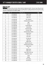
Страница 17: ...45 000 007 Oil cap 4 8 1345 000 008 Left Housing set 1 9 1345 000 009 Tension Bolt 1 10 1345 000 010 Extension Spring 1 11 1345 000 011 Pressure Plate 2 12 1345 000 012 Standard Spring Washer 3 13 134...

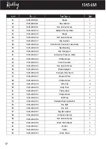
Страница 18: ...shion 1 44 1345 000 044 Hex Socket Screw 1 45 1345 000 045 Blade Adaptor 2 46 1345 000 046 Pressure Pole Knob 1 47 1345 000 047 Pressure Pole 1 48 1345 000 048 Philips Screw 2 49 1345 000 049 Wire Cli...

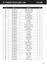
Страница 19: ...Circuit Board 1 77 1345 000 077 Eccentricity Knob 1 78 1345 000 078 Pin type B 1 79 1345 000 079 Spring Leaf 1 80 1345 000 080 Fixing Block 1 81 1345 000 081 Lock Nut M6 1 82 1345 000 082 Movable Blo...

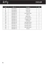
Страница 20: ...1345 000 101 Wire clip 2 102 1345 000 102 Philips screw 2 103 1345 000 103 Led circuit boad 1 104 1345 000 104 Transformer box 1 105 1345 000 105 Flat Washer 1 106 1345 000 106 Hex Socket Screw 1 107...

Страница 21: ...Two years for battery and charger This warranty does not include expendable parts including but not limited to blades brushes belts and light bulbs This warranty covers defects in material or workman...

Страница 22: ...21 226002 VS4005B...

Отзывы: