D2112/D2112E Installation Manual
Page 7
74-07111-000-D 1/96
© 1995 Radionics
Install Detection Devices,
Keypads, and Bells
No Connections to the Panel Yet
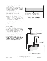
Install and wire detection devices, keypads, and
indicating devices (bells, sirens, or strobes for
example) at their locations throughout the premises.
DO NOT make the connections at the panel end of
the wiring yet.
Number of Sensors
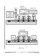
When using the D2112's Point 1 as a fire point, the
number of devices you can connect to it's sensor
loop is limited. See
Point 1 on the D2112 Only on
Page 10.
The number of sensors you can connect to the
sensor loops for points 2 to 8 (1 to 6 on D2112E) is
limited only by the resistance on the loop.
Resistance must be less than 100
Ω
with the
detection devices connected.
Continue Connections
to the Panel
Power Down First
Unplug the transformer and disconnect the battery to
make the remaining connections to the panel.
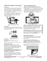
Alarm Output
Terminals 6 and 7
Terminals 6 and 7 provide a 10.2 VDC to 13.9 VDC
output when activated.
Terminal 6 provides a
steady positive output. Terminal 7 provides a
pulsed or steady negative output as programmed.
There is always power at Terminal 6: The D2112
sends a trouble report if terminal 6 is shorted to
ground. The D2112 sends a trouble report if terminal
6 is shorted to terminal 7 while the alarm output is
activated.
Use this power for bells, siren drivers, piezo fire
sounders, electronic horns, or other devices.
Available Power
The panel combines power produced by the power
supply with power from the secondary power source
(the battery) to produce a total of 1.5A of
alarm
power at terminals 6 and 7.
D126 Battery required for fire and combined fire/
burglary systems: In order to meet standby battery
requirements, use the Radionics D126, 12 V 7.0Ah
battery for fire and combined fire/burglary systems.
Power restricted for fire and combined fire/
burglary systems: Use the Fire System Power
Formula below to calculate the alarm current
available for fire and combined fire/burglary systems.
Fire System Power Formula
To calculate the current available at terminals 6 and
7 for fire and combined fire/burglary systems:
1. Add together the current draws for all devices
connected to terminal 9. This total is current
required for the Normal Standby Condition
(NSC). This total must be less than 140mA.
2. Subtract the NSC current required calculated in
step 1 from the Primary Alarm Current, 860mA.
The difference is the Alarm Current Available
for terminals 6 and 7.
In formula format:
Primary Alarm Current – NSC current required =
Alarm Current Available


