На нашем веб-сайте вы можете бесплатно скачать руководство по установке для продукта Radionics D2112. Это инструкция поможет вам правильно настроить и использовать устройство для достижения максимальной эффективности. Скачайте ее с manualshive.com.
D2112/D2112E Installation Manual
Page 1
74-07111-000-D 1/96
© 1995 Radionics
D2112/D2112E Control/Communicator
Installation Manual
Страница 1: ...D2112 D2112E Installation Manual Page 1 74 07111 000 D 1 96 1995 Radionics D2112 D2112E Control Communicator Installation Manual ...
Страница 2: ... 7 Part 68 This equipment complies with Part 68 of FCC rules A label contains among other information the FCC registration number and ringer equivalence number REN Radionics registered the D2112 Control Communicator for connection to the public telephone network using an RJ38X or RJ31X jack Use the ringer equivalence number REN to determine the number of devices you can connect to the telephone li...
Страница 3: ...iary Power Terminal 9 8 Testing and Replacing D2112E Fuses 9 External Relays Terminals 11 and 12 9 Connect the Points 10 Point 1 on the D2112 Only Terminals 13 and 14 10 Points 2 to 6 1 to 6 on D2112E Terminals 15 to 22 14 to 22 on D2112E 10 Points 7 and 8 on the D2112 Only Terminals 23 to 25 10 Program the Panel 12 Make the Telephone Connections 12 Power Up 12 Fill out the Point Chart 12 Unlock t...
Страница 4: ...for the features you want to use Have the following additional documents handy as you read through the manual D2112 D2112E Program Record Sheet D2112 D2112E Program Entry Guide Security System User s Guide Introduction D2112 D2112E Control Communicator The Radionics D2112 and D2112E Control Communicators are shipped pre assembled from the factory You should receive the following parts with your D2...
Страница 5: ...ng Run phone and sensor loop wiring away from AC conductors including the transformer wire Run keypad wiring away from AC and phone wiring EMI may also occur if you install the panel or run system wires near the following Computer network system Fluorescent fixtures Telephone cabling Ham radio transmitter site Heavy machinery and motors High voltage electrical equipment PBX telephone system Public...
Страница 6: ...l locally from the keypad or the D5200 Releasing the Standby Switch from the closed position resets the panel The panel resets all its timers and counters and clears all buffers Transformer Terminals 1 and 2 Connect the transformer to terminals 1 and 2 on the panel before plugging it into the power source Use 18 AWG wire to connect the transformer to the panel Wire length should be kept as short a...
Страница 7: ...ble report if terminal 6 is shorted to ground The D2112 sends a trouble report if terminal 6 is shorted to terminal 7 while the alarm output is activated Use this power for bells siren drivers piezo fire sounders electronic horns or other devices Available Power The panel combines power produced by the power supply with power from the secondary power source the battery to produce a total of 1 5A o...
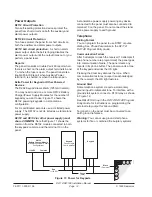
Страница 8: ... for your system Instructions for using stand alone power supplies are included Auxiliary Power Terminal 9 The continuous current draw for powered devices connected to terminal 9 including keypads must not exceed 350mA 140mA for fire and combined fire burglary systems Devices powered from this output must operate over a range of 10 2 VDC to 13 9 VDC You must use a minimum of five feet 22 AWG of wi...
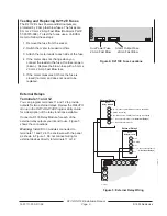
Страница 9: ...st the fuses use a Volt Ohm meter to follow these steps 1 Remove the fuse from the socket 2 Switch the meter to measure Ohms 3 Attach the meter leads to each side of the fuse 4 If the meter does not change when you connect the leads to the fuse the fuse is open blown Replace the blown fuse with a 5 mm x 20 mm 2 Amp Fast Blow fuse 5 If the meter measures 0 Ohms the fuse is closed normal and does no...
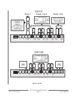
Страница 10: ...er limited by the Authority Having Jurisdiction Burglar Devices Connect any number limited by available power of burglar devices to any point Do not combine fire detection and burglar devices Points 2 to 6 1 to 6 on D2112E Terminals 15 to 22 14 to 22 on D2112E Points 2 to 6 1 to 6 on D2112E are supervised non powered points The panel monitors sensor loops for normal shorted or open conditions Prog...
Страница 11: ...r Loop suitable for Two Wire Smoke Detectors 6 8 K Ω Resistor required at End of Line For compatible smoke detectors see RPN 73 07115 000 Point 1 23 24 25 Point 7 Point 8 Unsupervised Points Open 2 4 13 9VDC Normal Closed 0 0 1 4VDC No End of Line Resistor D2112 15 16 17 20 21 22 19 18 Six Supervised Points Open 8 9 13 9VDC Normal 2 5 8 5VDC Short 0 0 2 0VDC 1 0 K Ω Resistor Required at End of Lin...
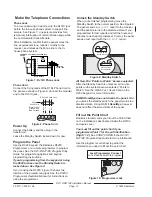
Страница 12: ...112E Program Entry Guide for more information Use the program record sheet to gather the information you need to fill out the point chart D164 Phone Cord 25 26 27 28 29 T1 R R1 T Brown Green Red Gray To RJ31X Phone Jack Black Yellow Orange and Blue not used Figure 8 Phone Cord Figure 7 RJ31X Phone Jack R1 T1 1 2 3 4 5 6 7 8 R T PREMISES PHONE INCOMING TELCO LINE FULL MODULAR PHONE JACK RJ31X MODUL...
Страница 13: ... report sent 13 0 VDC Battery restoral reports sent OK light on steady 13 9 VDC Battery float charged Test the System After finishing installation and programming make a complete functional test of the system Test the panel and all devices for proper operation Test after you first program the panel and after any subsequent programming session Clear after test To clear the alarm memory and report b...
Страница 14: ...e connected to both the keypads common and the terminal 10 on the panel A stand alone power supply powering any device connected to the panel must also be connected to terminal 10 on the panel Do not connect the stand alone power supply to earth ground Telephone Dialing Format You can program the panel to use DTMF or pulse dialing See Phone Parameters in the D2112 D2112E Program Entry Guide Commun...
Страница 15: ...ised with EOL resistors Open Loop Greater than 2 4 VDC but less than 13 9 VDC Normal Closed Loop Greater than 0 0 VDC but less than 1 4 VDC Point Response Time The panel scans point sensor loops every 500 milliseconds A point must be faulted for 2 scans before the panel initiates an alarm Short and restoral on circuit toggles arming state COMMON POINT INPUT End of Line Resistor Figure 13 Keyswitch...
Страница 16: ...ystem Off Program the Keyswitch Keyswitch prompt to Easikey See the D2112 D2112E Program Entry Guide for instructions You must use a 12VDC option for the Easikey installation See the Easikey Installation and Operation Instructions Connect the Easikey door controller to the panel using a D133 Relay Module as shown in Figure 14 Make certain to connect the common for the Easikey s 12VDC power supply ...
Страница 17: ...re initiating devices Consult the individual component specification and installation documents to determine suitability When using four wire smoke detectors install a suitable power supervision unit according to the manufacturer s instructions Use the D133 Relay Module to provide reset capability In fire applications with one 7 0Ah 12 VDC battery the panel supports an auxiliary output of 140mA an...
Страница 18: ...culations to verify compliance The formula below includes a 10 contingency factor for depletion of battery capacity with age NFPA 72 Ampere Hour Calculation Formula Total B ___ x 24 Hrs Total C ___ x 067 Hrs 10 Contingency Total Ah required Total Ah requirements must not exceed Ah capacity of batteries Current Rating Chart for Standby Battery Calculations All currents are in milliamperes 1 ampere ...
Страница 19: ...andard 2 Two or more required for this application Consult the appropriate standard 1 D2112 Only At least one detector required You can substitute other 2 wire detectors listed for use with the D2112 You could use the D262 with the D270 four wire base or other manufacturers four wire detectors You must use a listed power supervision relay with four wire detectors Listed bell siren housing required...
Страница 20: ...rm P S Supervised with 6 8k Ω EOL Resistor P S P S P S P S P S P P Arming Station D202 Up to Four D2112E P S P S P S D126 Battery 12V 7Ah P P P P S 16 VAC 25 VA 60 HZ Transformer D1240 Battery 12V 4Ah D1625 S P P D133 Relay P D133 Relay P P P S P S P S P Listed Audible Signaling Device Rated At 10 2 TO 13 9 VDC Do NOT Use Vibrating Type Horns Required for Fire and Combined Fire Burglary Optional f...
Страница 21: ...g in transformer D1625 Secondary Power Supply 12 VDC 4 0 Ah sealed lead acid rechargeable battery 7 0 Ah battery required for Fire and combined Fire Burglary systems Auxiliary Power Output 350mA maximum at 10 2 VDC to 13 9 VDC for devices powered at terminal 9 140mA for Fire and combined Fire Burglary systems Alarm Power Output 1 5 A maximum at 10 2 VDC to 13 9 VDC output Output may be steady or p...
Страница 22: ...eypad Data Data for Keypads 9 Auxiliary Power Positive Supplies 350mA at 10 2 to 13 9 VDC for auxiliary power keypads and relay outputs 10 Common Common for Auxiliary Power and Relay Drivers 11 External Relay 1 Connect D133 Relay for Form C Dry Contact 12 External Relay 2 Connect D133 Relay for Form C Dry Contact 13 D2112 Positive Point 1 Not used on D2112E D2112 Positive power for Point 1 Switche...
Страница 23: ...O I Menu Documents by Type Menu Documents by Product Menu Main Menu ...