© 2020 Radiodetection Ltd
27
Inductive search
An inductive search procedure is a more certain
technique for locating unknown lines. This type of search
requires a transmitter and locator and two people. This
type of search is referred to as a ‘two person sweep’.
Before starting the sweep, define the area of search and
the probable direction of lines crossing the area. Ensure
the transmitter is switched on in induction mode.
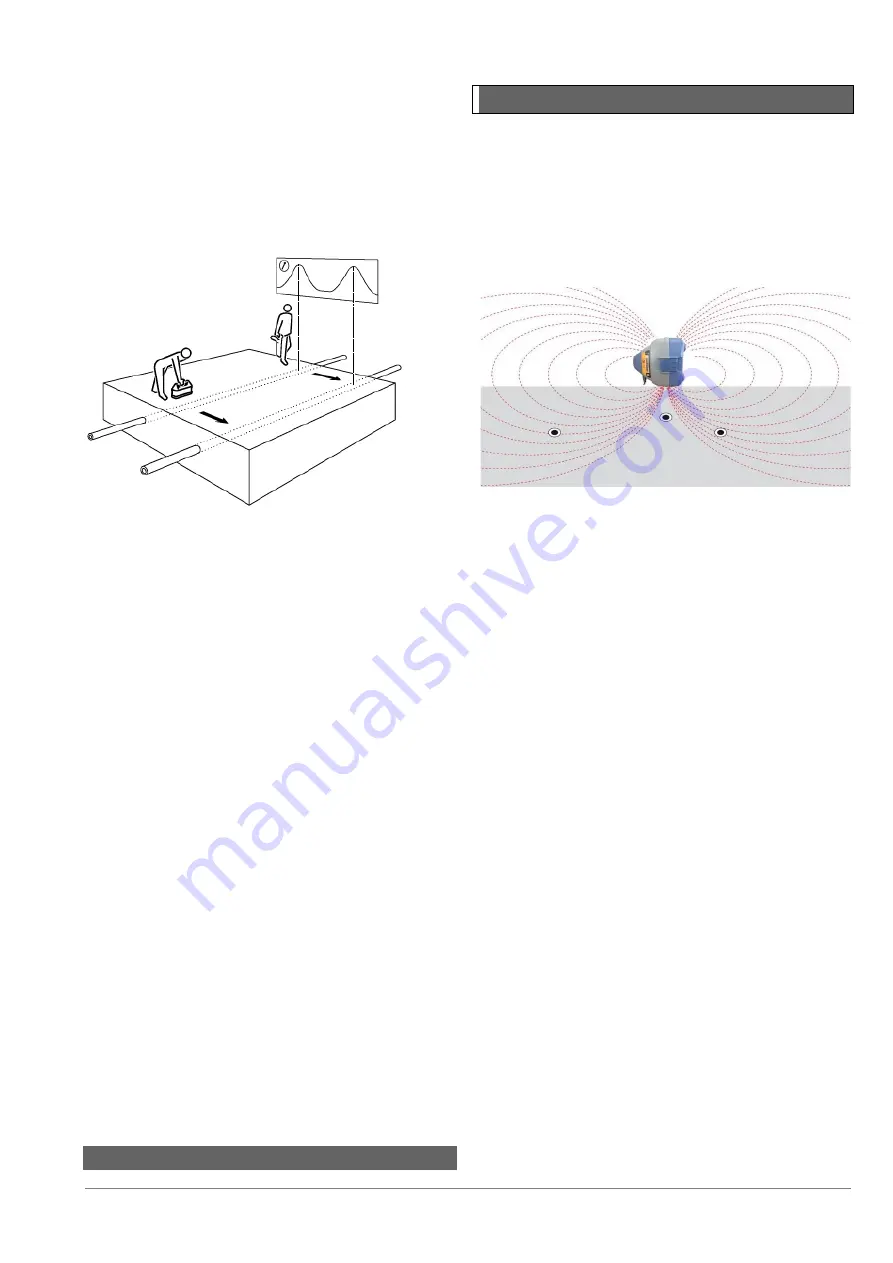
Figure 5.5: Inductive search
The first person operates the transmitter and the second
person operates the locator. The transmitter induces a
signal onto lines as it passes over them and the lines are
then detected with the locator at a suitable distance
away from the transmitter (around 15 meters / 50 feet
–
although this will depend upon the level of induction
power used.)
Hold the transmitter with its length aligned with the
assumed direction of any lines.
The second person holds the locator at the start of the
area to be searched and with the locator antennas at
right angles to the probable direction of the buried lines.
Set the locator sensitivity level as high as possible
without the locator picking up any airborne signals
directly from the transmitter.
When the transmitter and locator are in line both
operators start to move forward in parallel. The operator
with the locator sweeps it backwards and forwards,
keeping the locator vertical, as they proceed in parallel
with
the
transmitter.
This
method
allows
for
misalignment of the transmitter, locator and buried line.
The transmitter applies the strongest signal to the lines
directly below it, which are then located with the locator.
Move the transmitter from side to side to establish the
highest signal which indicates that the transmitter is also
directly above the line(s).
Mark the ground at the point of each Peak signal
detected with the locator. Repeat the search along any
other possible paths of lines. Once the positions of any
lines have been marked, reverse positions, place the
transmitter over and along each line in turn, and trace
the line out of the search area.
5.8
Nulling Out
Sometimes it is possible for some utilities to be masked
by other utilities and this can happen when one or more
utilities are in close proximity to each other or when
stronger signals may radiate. In certain applications and
congested areas the ‘Nulling’ technique allows operators
to eliminate the induction signal directly beneath the
transmitter but at the same time induces the transmitter
signal onto other nearby utilities that previously have not
been able to be located
Figure 5.6 Nulling Out effect
Two persons Nulling Out technique:
1. Place the transmitter close to the services you
wish to trace (a parallel sweep may be used for
this) and using the locator at a distance of
approximately 10m/30’ from the transmitter,
pinpoint the strongest signal.
2. The sensitivity on the locator
is adjusted so that
the bar graph response is approximately 75%
3. Release the side support arm.
4. With the locator over the centre of the signal
the second operator should hold the transmitter
at waist level, with the transmitter on its side
–
release support arm pointing down.
5. The transmitter is the
n
moved
from side to side
to find the ‘Null’ spot between two detectable
signals; the transmitter should then be lowered
towards the ground keeping it in the ‘Null’ spot.
6. At ground level we are ideally looking for a
‘Null’ no wider than 50mm/2” (Sensitivity on the
locator may need to be adjusted to achieve
this).
7. With the transmitter left on the ground in the
‘Null’ spot.
T
he locator is used to check for
additional
signals either side of the ‘Nulled’
signal.
8. Should the ground be uneven the transmitter
may be turned
across the line of the service
provided the release support arm remains
facing downwards. (this will improve the
stability of the unit)


