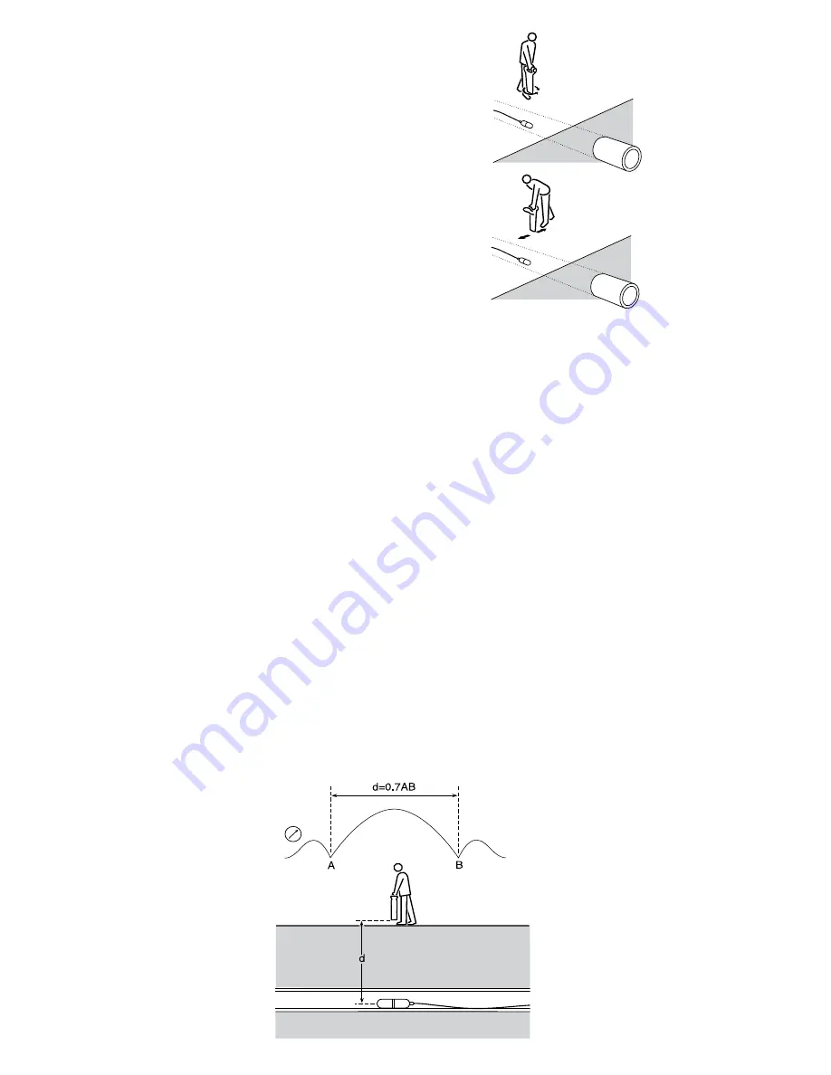
Stop when the bar graph indicates a
clear peak.
Rotate the Receiver until the blade’s
orientation is perpendicular to the
Sonde, stop when the bar graph
indicates a clear peak.
Move the Receiver from side to side
until the bar graph indicates a clear
peak.
When the Receiver locates a peak
signal, it will automatically calculate
the depth of the Sonde. Observe
the depth reading while moving the
Receiver from side to side; the lowest
reading will be the correct location.
2
3
4
5
Repeat each step in smaller increments with the Receiver blade resting
on or near the ground. The Receiver should now be directly above the
Sonde with the blade in line with the Sonde; mark this position.
Propel the Sonde a further three to four meters along the pipe and
pinpoint and mark. Repeat the procedure along the route at similar
intervals. Note, while tracking the Sonde altering the receiver’s sensitivity
is not required unless the depth pipe, or the distance between Receiver
and Sonde changes.
Measuring Sonde depth
Pinpoint the Sonde as previously described. Then rest the Receiver on
the ground with the blade’s orientation parallel to the orientation of the
Sonde. Adjust the sensitivity to give a meter reading of 60
%
to 80
%
on
the LCD’s bar graph.
Note that the depth reading is the distance from the bottom of the
Receiver blade to the center of the Sonde and not to the drain or duct
being located.
CAUTION: Ensure Depth readings are taken from peak readings.
Depth readings taken from ghost signal position will be incorrect.
Depth measurement is automatic. Depth reading will be displayed when
the Receiver is moved slowly across the Sonde. The shallowest depth
reading displayed on the LCD is also the correct position directly above
the Sonde.


