background image

Installation Manual  

Floor standing storage boiler – Cod. 99949NA – November  2002


10 

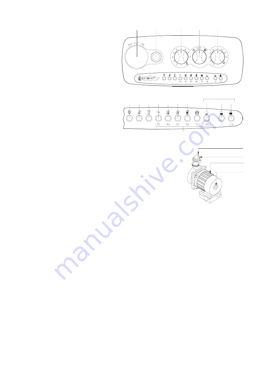
PUMP CAP

CIRCULATING PUMP

AIR VENT VALVE CAP

AIR VENT VALVE

CONTROL PANEL 


LEGEND

 (see fig. 1) 

1. 

SUMMER-WINTER ON-OFF SWITCH 

2. 

LOCK-OUT INDICATOR 

3. 

HEATING TEMPERATURE ADJUSTMENT KNOB 

4. 

WATER TEMPERATURE ADJUSTMENT KNOB 

5. 

SPACE FOR ADDING AN OPTIONAL TIMER 


SELF- DIAGNOSTIC

 LEGEND (see fig. 2) 

6. 

OPERATING/ POWER INDICATOR 

7. 

DOMESTIC HOT WATER OPERATION 

8. 

HEATING OPERATION  

9. 

FLASHING LIGHT DENOTING AIR PRESSURE SWITCH 

FAILURE 

10. 

FLASHING LIGHT DENOTING DOMESTIC WATER 

SENSOR FAILURE  

11. 

FLASHING LIGHT DENOTING HEATING SENSOR 

FAILURE  

12. 

FLASHING LIGHT DENOTING 90° C MAX 
TEMPERATURE SENSOR FAILURE  

13. 

FLASHING LIGHT DENOTING LACK OF WATER IN 
SYSTEM 

14. 

WATER PRESSURE LEVEL 1 BAR 

15. 

WATER PRESSURE LEVEL 1.5 BAR 

16. 

ELECTRONIC TEMPERATURE INDICATOR 


STARTING UP THE BOILER 

After connecting up the water supply, before starting up the boiler, carry out the 

following procedures: 


Preliminary procedure 

• 

Do as follows: 

• 

make sure the power supply for the boiler is the same as that stated on the plate 
(230V - 50Hz) and that the live, neutral and earth connections have been 

properly connected; 

• 

make sure the type of gas being supplied is the same as the type for which the 
boiler has been tested and approved (see plate data); 

• 

make sure the unit is properly earthed; 

• 

make sure there are no flammable liquids or materials in the immediate vicinity of the boiler; 

• 

make sure that any shut-off valves in the heating circuit are open; 

• 

open the gas cock and check the gas seals, making sure the counter shows no sign of leaks; in any case, double check by 
using a soapy solution and eliminate all eventual leaks. The checking procedure for the gas burner attachment is carried out 

with the boiler working; 

• 

make sure the electrical mains switch is OFF; 

• 

remove the front cover by pulling it forwards; 

• 

undo the side screws and rotate the panel downwards  


Filling the system


After making sure the gas cock is closed, fill the heating system as follows; 

• 

fill the system until a pressure of 1.5 bar has been reached (light no. 15 ON; see fig. 2) and then close the tap on the filling 
loop; 

• 

make sure the cap on the auto air vent valve is slightly loose to allow air to escape from the system (see fig. 1); 

• 

undo the cap on the circulation pump to eliminate any eventual air locks (see fig. 1). It is a good idea to purge all radiators of 
air at this point too; 

• 

before starting up the boiler the water pressure must be checked again; if this is seen to be below 0.5 bar (light no. 13 

flashes; see fig. 2), bring it back up to 1.5 bar (light no. 15 ON; see fig. 2) and close the tap on the filling loop 

• 

 switch on the electrical power supply to the boiler; 

• 

turn selector switch 1 to the WINTER   position (see fig. 1), after a few seconds the pump will come into action; 

• 

once the boiler is working, if any noises are heard in the system, repeat the above air purging procedures until there is no air 
left in the system; 

• 

check there are no obstructions in the exhaust duct; 


2

3

1

4

6

7

8

9

10

11

12

ELECTRONIC WATER

PRESSURE GAUGE

SELF-DIAGNOSTIC

5

13

14

15

16

Fig. 1 

Fig. 1


Fig. 2


Содержание Slim RBA CS 24 E

Страница 1: ...ion RADIANT BRUCIATORI S p A Montelabbate PU ITALY By Technical Department INSTALLATION AND MAINTENANCE MANUAL FOR FLOOR STANDING TYPE GAS BOILERS WITH DOMESTIC HOT WATER STORAGE CYLINDER Model RBA CS 24 E RBA CS 100 E TYPE C ROOM SEALED ...

Страница 2: ......

Страница 3: ...e 5 BOILER INSTALLATION page 7 ELECTRICAL CONNECTIONS page 9 21 22 BOILER CONTROL PANEL page 10 STARTING UP THE BOILER FOR THE FIRST TIME page 10 BOILER ADJUSTMENTS page 12 MULTIGAS OPERATION page 13 REGULATING THE GAS PRESSURE page 14 MAIN COMPONENTS page 15 17 MAINTENANCE page 23 UNPACKING page 23 FAULT FINDING CHART page 24 SHORT LIST OF COMPONENTS page 25 ...

Страница 4: ...pped with an expansion vessel 2 WARNINGS REGARDING INSTALLATION Warranty expires 12 months from date of installation and in all cases no later than 18 months from date of construction First start up must be performed by authorised personnel only For any operation on the hydraulic gas or electrical circuit regarding the heating unit refer to authorised technicians only and use original spare parts ...

Страница 5: ...12900 12900 Heting temperature adjustment C 30 80 30 80 Max working pressure heating bar 3 3 Min working pressure heating bar 0 3 0 3 Expansion vessel capacity initial pressure 1 bar Litres 10 8 Hot stored water max temperature C 60 60 Continuous hot water drawing with t 30 Litres h 807 858 Maximum continuous mixed drawing with t 30 first 10 minutes Litres 175 255 Max working pressure water bar 6 ...

Страница 6: ...ct and the air intake directly from an external wall To insert a bend reduce total flue length by 1 5 m R RETURN G GAS C HOT WATER OUTLET F COLD WATER INLET A HEATING FLOW NOTE USE ORIGINAL RADIANT APPROVED FLUE KIT SYSTEMS FLUE ACCESSORIES AND FLUE DIAPHRAGMS ONLY APPROVED RADIANT FLUE DIAPHRAGMS AND ADJUSTMENT TABLES ARE SUPPLIED WITH RADIANT ORIGINAL FLUE KIT SYSTEMS 258 600 100 60 100 60 763 8...

Страница 7: ...ke directly to an external wall To insert a bend reduce total flue length by 0 8 m NOTE USE ORIGINAL RADIANT APPROVED FLUE KIT SYSTEMS FLUE ACCESSORIES AND FLUE DIAPHRAGMS ONLY APPROVED RADIANT FLUE DIAPHRAGMS AND ADJUSTMENT TABLES ARE SUPPLIED WITH RADIANT ORIGINAL FLUE KIT SYSTEMS Kit B Double exhaust emission twin flue system with 360 rotation It allows the flue exhaust into a flue duct and the...

Страница 8: ...pework that supplies the boiler must be a 22 mm ininterrupted supply from meter to the isolation cock of the boiler The complete installation must be tested for soundness as described in the above code BS 6400 1985 BS6891 IMPORTANT BOTH THE USER AND THE MANUFACTURER RELY UPON THE INSTALLER WHOSE JOB IS TO INSTALL THE BOILER AND CONNECT IT TO A CORRECTLY DESIGNED HEATING SYSTEM THE INSTALLER SHOULD...

Страница 9: ...gion consulted Where the lowest part of the terminal is fitted less than 2m 6 6ft above a balcony above ground or above a flat roof to which people have access the terminal MUST be protected by a purpose designed guard Where the terminal is fitted within 850mm 34in of a plastic or painted gutter or 450mm 18in of painted eaves an aluminium shield of at least 1000 mm 40in long should be fitted to th...

Страница 10: ... function Install a funnel with discharge under the safety valve calibrated to 3 bar to collect water in case of leaking due to overpressure avoid using pipelines of reduced diameter avoid the use of tight bends and adapters in important sections clean out the system thoroughly before connecting up the boiler in order to eliminate any residue left in the pipes and radiators N B Make sure that the ...

Страница 11: ...r and 4 C Hot water sensor and protects the boiler down to 2 C external temperature To protect the internal Radiators a room thermostat or remote control must be fitted NOTE The frost system will only come into operation if the boiler is filled with water and connected to a live gas supply with electrical supply and boiler controls in the ON position With the Main switch turned to Summer or Winter...

Страница 12: ... the housing and open the electrical control box by lifting the cover as shown in fig 1 E With the electrical control box now open make the following connections Connect the yellow green wire to the terminal marked with the earth symbol see fig 1 Connect the blue wire to the terminal marked with the letter N Connect the brown wire to the terminal marked with the letter L CONNECTION OF ROOM THERMOS...

Страница 13: ...shut off valves in the heating circuit are open open the gas cock and check the gas seals making sure the counter shows no sign of leaks in any case double check by using a soapy solution and eliminate all eventual leaks The checking procedure for the gas burner attachment is carried out with the boiler working make sure the electrical mains switch is OFF remove the front cover by pulling it forwa...

Страница 14: ...nd check that the maximum pressure is equal to that stated on the plate to check the minimum undo one wire from the modulator coil and check on the gauge that the minimum pressure is equal to that stated on the plate if the maximum pressure is not the same as stated on the plate calibrate the modulator again once the calibration procedure has been completed unplug the mains lead or turn off the ma...

Страница 15: ...er for any adjustments Turn clockwise to increase gas pressure to the burner at start up by setting the trimmer to maximum calibration pressure of modulator see page 16 Turn counter clockwise to decrease gas pressure to the burner at start up by setting the trimmer to the minimum pressure at start up will correspond to minimum calibration pressure of modulator see page 16 Through the RLA commutato...

Страница 16: ...type of gas used undo fixing nut 8 on the thin aluminium gas pipe 9 and change the jet g replace the gas setting plate that indicates the type of gas and nominal pressure for the boiler When converting the boiler to work with a different type of gas remove the existing plate and replace it with the new one supplied in the conversion kit h calibrate the new max and min settings for the modulator DA...

Страница 17: ...Fig C Slide out the coil 1 located above the gas valve Fig D Tighten plastic screw 3 by turning it clockwise be careful not to break it Fig E Use a no 17 spanner to undo the lock nut 5 which holds the core 4 of the coil in place undo the screw and insert a pressure gauge Fig F Turn on the boiler regulate the maximum pressure by turning the core 4 clockwise to increase pressure counter clockwise to...

Страница 18: ... restore the initial position separate the actuator and the valve body following instructions from no 1 to no 4 see fig 1 To separate the motor from the valve body proceed as follows fig 1 1 Press button A under the motor 2 Simultaneously keep the A button pressed and turn the actuator counter clockwise 3 Lift off the motor 4 To disconnect the power supply cable press the B tap located on the pin ...

Страница 19: ...he specific boiler output FLOWSWITCH This device gives precedence to domestic hot water and is fitted to boilers which supply instantaneous hot water see fig 2 item B fig 3 It allows conversion to hot water even with a minimum hot water demand 2 litres min using an electromagnetic principle with electrical switching by means of a relay The device is made of non toxic corrosion proof ZYTEL 101 L pl...

Страница 20: ...ULATION PUMP WITH AIR VENT 17 AUTOMATIC AIR VENT 18 HEATING CIRCUIT 3 bar PRESSURE RELIEF VALVE 19 BOILER SAFETY VALVE SBS 2821 20 DRAINING TAP 21 WATER PRESSURE GAUGE 22 WATER PRESSURE SWITCH 23 HEATING SENSOR 24 HOT WATER SENSOR 25 3 WAY DIVERTER VALVE 26 FLOWSWITCH CONNECTION WITH FLOW LIMITER 27 ELECTRONIC FLOWSWITCH 28 BY PASS 29 BOILER DRAING TAP 30 45 LITRE WATER STORAGE TANK 31 100 LITRE W...

Страница 21: ... LED5 C6 C7 RS1 R58 R22 R21 4 2 1 3 15 14 22 LED2 LED1 LED3 LED4 RAVI II R31 42 R18 R17 yellow blue R48 FA1 C20 R49 R23 R24 R47 C19 C21 red brown R39 C9 M9 R62 R61 R57 J16 R38 C5 J20 R37 41 R16 C14 IC2 J7 T4 1 2 3 5 4 GPL C15 R40 R56 MET R43 R33 R15 R32 43 C13 C26 R42 44 45 R41 47 J21 R36 46 D12 61 R34 24 17 16 18 19 21 20 LED8 LED6 LED7 LED9 LED10 LED11 J2 M1 D2 8 7 6 5 J3 3 4 2 1 35 36 C8 J9 C3 ...

Страница 22: ...RSA RTA T SAN RLA T RIS 50 49 51 MAX RIS 60 53 55 54 RVB 40 30 57 56 50 58 RV 80 70 17 23 19 24 18 22 12 13 12 11 EA 8 ER 6 RPA P 15 PTC2 14 5 20 21 V RVA 16 2 1 3 7 4 PA VD NET FILTER IG R CY CY CX N L AIR PRESSURE SWITCH FAN PUMP RELAY CONTACT D H WATER RELAY CONTACT FAN RELAY CONTACT THERMOSTAT RELAY CONTACT FLOWSWITCH MICRO SWITCH 3 WAY DIVERTOR VALVE WIRING CONNECTION ONLY FOR Mod VC6012 D H ...

Страница 23: ...lers thermocouple for pilot light boilers Check the flue exhaust safety Check the minimum and maximum modulation pressure and the modulation Check that the electrical connection conforms to the description in the instruction manual for the boiler Check domestic water flow rate and temperature UNPACKING For RBA CS 24 E models Fig 1 Cut the black straps Lift up the cardboard box Push the boiler on o...

Страница 24: ... or rep q r lace it s replace it t change over polarity 4 Boiler on temperature rises rapidly and extinguishes flame light 2 fig 1 on u circulation pump burned out or blocked v air in system w flowswitch jammed open x heating system turned off u unblock or replace it v bleed system w unblock or replace it x open heating system cut off valve 5 Noise as flame ignites y ignition electrode wrongly pos...

Страница 25: ...ER PRESSURE SWITCH 1 8 15 96008LA 3 BAR PRESSURE RELIEF VALVE 1 2 16 96009LA D H W CYLINDER TEMP 90 PRESS 7BAR SAFETY VALVE 17 95011LA 8 LT EXPANSION TANK 18 95006LA 10 LT EXPANSION TANK 19 20031LA INSULATED 45 LT STORAGE CYLINDER 20 20022LA INSULATED 100 LT STORAGE CYLINDER 21 96007LA ELECTRONIC FLOWSWITCH 1 2 CONNECTIONS 22 37008LA EXHAUST FAN 230V 23 59006LB AIR PRESSURE SWITCH CE C6065AH1095 2...

Страница 26: ...01329 828555 All descriptions and illustrations contained in this leaflet have been carefully prepared but we reserve the right to make changes and improvements in our products whitch may affect the accurancy of the information contained in this leaflet E OE All rights reserved No part of this document may be reproduced saved in storage systems or transmitted in any form or by any means whether el...

Страница 27: ......

Страница 28: ......

Страница 29: ......

Страница 30: ......

Страница 31: ......

Страница 32: ......

Страница 33: ......

Страница 34: ......

Страница 35: ...CE 0694 ENGLISH Technical Specification RADIANT BRUCIATORI S p A Montelabbate PU ITALY By Technical Department USER MANUAL Models RBA CS 24 E RBA CS 100 E TYPE C ROOM SEALED ...

Страница 36: ...TEMPERATURE ADJUSTMENT KNOB 4 WATER TEMPERATURE ADJUSTMENT KNOB 5 SPACE FOR ADDING AN OPTIONAL TIMER SELF DIAGNOSTIC LEGEND see fig 2 6 OPERATING POWER INDICATOR 7 DOMESTIC HOT WATER OPERATION 8 HEATING OPERATION 9 FLASHING LIGHT DENOTING AIR PRESSURE SWITCH FAILURE 10 FLASHING LIGHT DENOTING DOMESTIC WATER SENSOR FAILURE 11 FLASHING LIGHT DENOTING HEATING SENSOR FAILURE 12 FLASHING LIGHT DENOTING...

Страница 37: ...ler locks out fig 1 page I indicator no 2 ON proceed as follows wait approximately 3 minutes from the last shut down press red reset button 2 fig 1 page I The boiler comes into operation If lock outing persists turn the boiler OFF and call RADIANT HELP LINE 01329 828555 WARNINGS FOR THE USER To keep the boiler in efficient and safe operating condition carefully follow the instructions listed below...

Страница 38: ...01329 828555 All descriptions and illustrations contained in this leaflet have been carefully prepared but we reserve the right to make changes and improvements in our products whitch may affect the accurancy of the information contained in this leaflet E OE All rights reserved No part of this document may be reproduced saved in storage systems or transmitted in any form or by any means whether el...

Отзывы: