12
R2KA 28 /20 - RAD - ING - Manuale - 1806.1_SK.2
1 Sp
azi
te
cn
ici minimi
e p
osizionamento
_m
ur
al
e_
R
2K
A
_.2
0_
R
2K
A
_.8
_E
N
1. INSTALLATION
INST
ALLER
1.1.7. POSITIONING AND MINIMAL
TECHNICAL SPACES
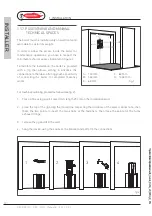
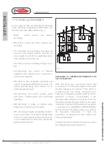
The boiler must be installed only on a vertical solid
wall, able to sustain its weight.
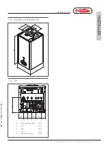
In order to allow the access inside the boiler for
maintenance operations, you have to respect the
minimum technical spaces indicated in figure 1.
To facilitate the installation, the boiler is provided
with a jig that allows setting in advance the
connections to the tubes offering you the possibility
of connecting the boiler to completed masonry
works.
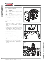
For machine positioning, proceed as follows (see fig. 2):
1. Trace a line using a spirit level (min. length 25 cm) on the installation wall.
2. place the top of the jig along the traced line respecting the distances of the water connections; then
mark the two points to insert the two knobs or the fasteners, then trace the points for the fume
exhaust fittings;
3. remove the jig and drill the wall;
4. hang the device using the knobs or the bracket and perform the connections.
3
1
4
2
70
80
102
49
31
78
Ø80
Ø125
Ø100
358
26
26
54
54
821
681
699
302
785
H
B
A
Y
X
A -
500
mm
B - 300 mm
X - 60 mm
Y - 60 mm
H - 1000 mm
fig.1
fig.2


