background image


Radiant, Inc. 


11 


Step Four (Rev B Hardware):


Connect the HOST RS232 connector (See Figure 5) to a host PC serial port using a 6 

conductor phone wire to the RJ12<->9 pin male/female adapter.  Connection to the DB9 

side requires only three wires for pins 2, 3, and 5. 
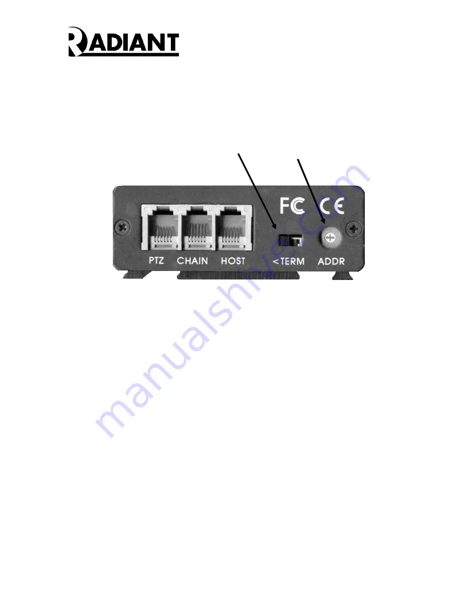


RS485 Termination

Switch for CHAIN

Address Switch

(FF0-FFF)


Figure 5 – DVMD1 Rev B Rear Panel 


Step Five:


Set  the  Unit  Address  switch  to  “0”  for  single  DVMD  installations.  All  DVMD  units  are 

mapped into the address range 0xFF0 to 0xFFF.  The Unit Address rotary switch selects 

the least significant digit (0-F).  Turn the rotary switch to “0” to select Unit Address 0xFF0. 

(See Figure 5)  For systems with multiple DVMD units, chained together by the RS485 

bus, each individual Unit Address switch must be set to a unique number from “0” to “F”.  

The physical Unit Address must match the last digit entered in the “Unit Address” menu in 

the user interface.    


Step Six:


The RS485 CHAIN switch must be terminated for the first and last units in the CHAIN.  All 

other DVMD1 termination switches must NOT be terminated.  A six-conductor phone wire 

may be used to connect from the CHAIN output of the first unit (FF0) to the next unit. 


The REV A  product has separated CHAIN  inputs.  The Rev B products use the HOST 

connector  for  two  functions:  RS232  to  the  host,  and  as  the  CHAIN-IN  connection  for 

subsequent units on the RS485 bus.  The CHAIN cables may be up to 100 feet in length, 

with a total length of 1000 feet.  The CHAIN phone cables are crimped with the white wire 

to the right with the tab up on both ends of the cable. 


Содержание DVMD1

Страница 1: ...Hardware User s Manual Digital Video Motion Detector DVMD1 Revision B October 2004 Radiant Inc 2395 Kenwood Drive Boulder CO 80303 303 543 0440...

Страница 2: ...is a manual for the installation setup and configuration of the DVMD1 It contains step by step instructions for connecting the DVMD1 in a system It outlines a variety of set up features The minimum D...

Страница 3: ...e Video Processor processes the incoming video with internal processing including DC restoration clamping automatic gain control AGC and filtering It generates an overlay for the time date camera numb...

Страница 4: ...ng a variety of settings A security system with multiple video cameras may use multiple DVMD1 units that are chained together Within such a system each unit must be assigned a unique address Chaining...

Страница 5: ...Y USER ALARM PANEL HOST COMPUTER Figure 2B DVMD1 Connected to Host Configuration Figure 1C illustrates a block diagram of three DVMD chained together by the RS485 serial link The host communicates to...

Страница 6: ...power opto isolated input and dry contact relay alarm output The opto isolated input is active when driven from an external voltage source between 4 to 24 volts The function of the opto isolated inpu...

Страница 7: ...e right with the tab up RJ12 PIN NUMBER COLOR FUNCTION Pin 1 WHITE RS232 Data Transmitted to PC Pin 2 BLACK Ground Pin 3 RED CHAIN RS485 Data Pin 4 GREEN CHAIN RS485 Data Pin 5 YELLOW Ground Pin 6 BLU...

Страница 8: ...ed by the output of a a one shot that is triggered on the negative going edge of each bit and lasts for 3 4 character times at 300 baud for full duplex operation PROTOCOL JUMPERS Two PROTOCOL jumpers...

Страница 9: ...Radiant Inc 9 Table 3 Internal Jumper Settings...

Страница 10: ...ound to V These screw connectors are located on the Front Panel of the DVMD See Figure 4 Figure 4 DVMD Front Panel Step Two Connect a 75 ohm Coaxial Cable from the VOUT BNC connector located on the DV...

Страница 11: ...d together by the RS485 bus each individual Unit Address switch must be set to a unique number from 0 to F The physical Unit Address must match the last digit entered in the Unit Address menu in the u...

Страница 12: ...utput to the Auxiliary Input Auxin screw terminals Force the output bit high to disable the DVMD1 alarms and put the product into PAN mode The PAN overlay will appear Move the PTZ camera to the desire...

Отзывы: