background image

Log settings

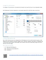
To adjust the logging mode and the log rate of the VBOX Micro, open the ‘Logging’ tab in VBOX Setup.

Once the logging mode and rate have been set, click the ‘Write Settings’ button to program the new configuration into
the VBOX Micro.

The log rate is shown as a frequency (in Hz) and also as a time period (in ms). Both options are linked so if one is
altered the other setting will automatically reflect the change.

Time/Date

The VBOX Micro uses time and date information available from GPS satellites. This time is based around UTC
(approximately equal to GMT) so if the VBOX Micro is used in a different time zone the local time should be set inside
the VBOX Micro for ease of use.

As the time and date are critical to the creation of file names in the VBOX Micro, it is recommended that the local time is
correctly set.

Adding or subtracting an offset on the GPS page of VBOX Setup adjusts the local time.

Once the offset has been set click the ‘Write Settings’ button to program the new time and date into the VBOX Micro.

NOTE: In order to obtain UTC time, the VBOX Micro must have attained satellite lock.

https://racelogic.support//01VBOX_data_loggers/VBOX_Micro/VBOX_Micro_-_User_manual/05_-_VBOX_Micro_Configuration

13

Содержание VBMIC01C

Страница 1: ...icro Logging 04 VBOX Micro Satellite lock 05 VBOX Micro Configuration 06 VBOX Micro Connecting an Input module 07 VBOX Micro Connecting a Display 08 VBOX Micro Upgrading firmware 10 VBOX Micro PIN OUT...

Страница 2: ...biker The slowest recording rate is 1 sample per minute which is useful for more long term testing such as vehicle endurance testing mileage route analysis or even the movement of a ship VBOX Micro lo...

Страница 3: ...le Earth Measure acceleration figures top speed mile etc Take it anywhere IP66 sealed against water mud dust etc Choose a sample rate from 10 times a second to once per minute Attach input modules to...

Страница 4: ...hicles have a CAN bus and each manufacturer uses a different protocol However we can supply CAN sets for various manufacturers see the vehicle CAN database section on our website for details VBOX Micr...

Страница 5: ...Micro This is necessary because on power up the VBOX Micro will look for a connected GPS antenna and automatically adjust its gain for optimum performance See technical specification page for voltage...

Страница 6: ...unications via USB Illuminates YELLOW to indicate CAN communications LOG Illuminates GREEN indicating data is being logged to the CF card https racelogic support 01VBOX_data_loggers VBOX_Micro VBOX_Mi...

Страница 7: ...tup This allows the log rate to be set in the range between 1 sample per minute and 10 samples per second 10 Hz File Management VBOX Micro data files are stored in Month folders on the CF card i e Jan...

Страница 8: ...efore use Should the CF Card need formatting due to card errors it can be done through Windows as the VBOX Micro supports the following format type FAT up to 2 GB FAT32 up to 128 GB Racelogic strongly...

Страница 9: ...antennae are available by contacting your VBOX Micro distributor The antenna is a magnetic mounting type for quick and simple mounting to the vehicle roof For optimum GPS signal reception make sure t...

Страница 10: ...has an internal ground plane and can operate perfectly without the need for mounting on a metal surface Ground plane antennas are available from your VBOX distributor part number RLVBACS065 Coldstart...

Страница 11: ...ort on the VBOX Micro to one of the computers USB ports When connecting to VBOX Setup use the drop down list to select the COM port assigned to the VBOX Micro Once this is selected VBOX Setup will con...

Страница 12: ...celogic setting file RSF 5 Language Select an operating language 6 Diagnostics Live preview of satellites latitude longitude velocity accumulative distance 7 GPS Information Reports the internal GPS e...

Страница 13: ...s time is based around UTC approximately equal to GMT so if the VBOX Micro is used in a different time zone the local time should be set inside the VBOX Micro for ease of use As the time and date are...

Страница 14: ...D connector female 1 m CAN cable RLCAB019F 9 way D connector male to OBDII connector 1 2 m RLVBCAB20 Enabling VCI Mode Connect the VBOX Micro to the computer via the USB cable Run VBOX Setup Select th...

Страница 15: ...her Racelogic products For a VCI channel to be included in the logged file it must be Ticked as shown on all the channels in the screen shot below https racelogic support 01VBOX_data_loggers VBOX_Micr...

Страница 16: ...s baud rate is configured by selecting the desired baud rate from the right hand side of the VBOX Setup CAN tab https racelogic support 01VBOX_data_loggers VBOX_Micro VBOX_Micro_ _User_manual 05_ _VBO...

Страница 17: ...atabase file From each channels setup window a CAN database file can be loaded by clicking the Database button Clicking the Database button allows a CAN database file to be opened and then a signal fr...

Страница 18: ...ADC03 RLCAB063 4 Channel Frequency and Pulse Counter Input Module RLVBFIM03 RLCAB063 Mini Input Module RLVBMIM01 RLCAB063 Yaw Rate Sensor 2 Axis G Sensor RLVBYAW03 RLCAB065 Inertial Measurement Unit R...

Страница 19: ...ters plus the ability to show live results of acceleration and deceleration runs and also display Lap times For details of full functionality please refer to the Multi Function Display user manual Whi...

Страница 20: ...brake test results https racelogic support 01VBOX_data_loggers VBOX_Micro VBOX_Micro_ _User_manual 07_ _VBOX_Micro_Connecting_a_Display 20...

Страница 21: ...r in this manual before following the instructions below How to Upgrade the Firmware Press and hold the button whilst the power is connected to the VBOX Micro The VBOX Micro will enter Upgrader mode i...

Страница 22: ...nfigure the VBOX Micro internal settings can be downloaded from the link below https www vboxautomotive co uk index php en customer area software https racelogic support 01VBOX_data_loggers VBOX_Micro...

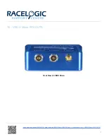
Страница 23: ...10 VBOX Micro PIN OUTS Front View of VBOX Micro https racelogic support 01VBOX_data_loggers VBOX_Micro VBOX_Micro_ _User_manual 10_ _VBOX_Micro_PIN_OUTS 23...

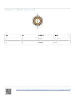
Страница 24: ...Connector 1 POWER Fischer 2 PIN PIN I O Function Range 1 I Power 6 30 V 2 I Ground 0 V https racelogic support 01VBOX_data_loggers VBOX_Micro VBOX_Micro_ _User_manual 10_ _VBOX_Micro_PIN_OUTS 24...

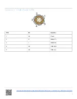
Страница 25: ...COMS Fischer 5 PIN PIN I O Function 1 I O Power 2 O RS232 Tx 3 I RS232 Rx 4 I O CAN High 5 I O CAN Low https racelogic support 01VBOX_data_loggers VBOX_Micro VBOX_Micro_ _User_manual 10_ _VBOX_Micro_...

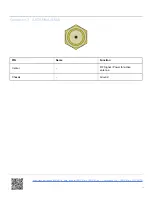
Страница 26: ...nector 3 ANTENNA SMA PIN Name Function Center RF Signal Power for active antenna Chassis Ground https racelogic support 01VBOX_data_loggers VBOX_Micro VBOX_Micro_ _User_manual 10_ _VBOX_Micro_PIN_OUTS...

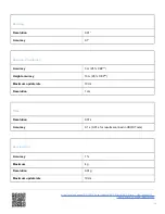
Страница 27: ...pdate rate 10 Hz Maximum velocity Minimum velocity 1000 mph 0 1 km h Resolution 0 01 km h Latency 160 ms Distance Accuracy 0 05 50 cm per km Units m ft Maximum update rate 10 Hz Resolution 1 cm https...

Страница 28: ...pdate rate 10 Hz Resolution 1 cm Time Resolution 0 01 s Accuracy 0 1 s 0 01 s for results scanned in VBOX Tools Acceleration Accuracy 1 Maximum 4 g Resolution 0 01 g Maximum update rate 10 Hz https ra...

Страница 29: ...0 A Data available Satellites UTC time Latitude Longitude Speed Heading Altitude Vertical velocity Longitudinal and Lateral acceleration Distance since reset Power Input Voltage range 6 30 V DC Curren...

Страница 30: ...le CEP 95 of the time the position readings will fall within a circle of the stated diameter Module Dimensions https racelogic support 01VBOX_data_loggers VBOX_Micro VBOX_Micro_ _User_manual 12_ _VBOX...

Страница 31: ...https racelogic support 01VBOX_data_loggers VBOX_Micro VBOX_Micro_ _User_manual 12_ _VBOX_Micro_Technical_Specification 31...

Страница 32: ...AB010F VBOX Carry Case RLACS106 USB A USB Mini B 2 m RLCAB066 2 Optional Accessories Cables Description Product Code 5 way Fischer to 9 way D connector female 1 m CAN cable RLCAB19F 9 way D connector...

Страница 33: ...l 16 bit Analogue Interface RLVBADC03 Yaw Rate sensor 2 Axis G sensor IP65 RLVBYAW03 Inertial Measurement Unit IP65 RLVBIMU04 Antennas Description Product Code Low Profile Ground Plane Antenna RLACS10...

Отзывы: