TEX1003TFT
29
/ 34
User Manual
Rev. 1.1 - 27/05/21
7. Principles of Operation
There is a schematic view of the modules and connections that make up the
TEX1002 TFT
in figure 7.1.
DRIVER
MAIN BOARD
LPF +
DIRECT. COUPL.
BIAS
PANEL
TELEMETRY
INTERFACE
POWER SUPPLY
TFT
INPUT
(AUDIO/RDS)
R.F.
OUTPUT
MAINS
24V
1 X 46VDC
VPA (46VDC)
2 X VPA (46VDC)
FWD PWR
RFL PWR
BIAS
PS ALARM
VOLTAGE REG.
INTERFACE
FAN
R.F.
SPLITTER
COMBINER
R.F.
2 X R.F.
2 X R.F.
R.F.
RF MODULES
Figure 7.1
A brief description of the functions of each module is given below, and the complete
diagrams and layouts of the boards can be found in the “Technical Appendix” Vol.2.
7.1 Panel board
The panel board contains the microcontroller that implements the control and
management software of the device, the display and the other elements needed
to interface with the user.
The board interfaces with the other modules of the device, providing for the
distribution of power supplies, control signals and measurements.
7.2 Motherboard
The main board performs the following functions:
• Processing of audio, MPX and SCA inputs;
• Selection of input impedance
• 15 kHz filtering of the R and L channels
•
Preemphasis
Содержание TEX1003TFT
Страница 1: ...TEX1003 TEX1003TFT TFT USER MANUAL VOLUME1 Manufactured by R V R ELETTRONICA Italia ...
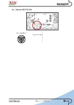
Страница 41: ...TEX1003TFT 35 34 User Manual Rev 1 1 27 05 21 9 4 Option CNT7 8 150 R F OUTPUT Type 7 8 50Ω ...
Страница 42: ...36 34 User Manual Rev 1 1 27 05 21 TEX1003TFT This page was intentionally left blank ...


