R.V.R. Electronica PJ500C-LCD Скачать руководство пользователя страница 5

1 / 32

User Manual

Rev. 1.

0

 - 15/12/06

PJ500C-LCD & PJ1000-LIGHT


1.  Preliminary Instructions

This manual is written as a general guide for those having previous 

knowledge  and  experience  with  this  kind  of  equipment,  well 

conscious  of  the  risks  connected  with  the  operation  of  electrical 

equipment.

It is not intended to contain a complete statement of all safety 

rules which should be observed by personnel in using this 

or other electronic equipment.

The  installation,  use  and  maintenance  of  this  piece  of 

equipment involve risks both for the personnel performing 

them and for the device itself, that shall be used only by 

trained personnel.

R.V.R. Elettronica SpA

 doesn’t assume responsibility for 

injury  or  damage  resulting  from  improper  procedures  or 

practices by untrained/unqualified personnel in the handling 

of this unit.

Please observe all local codes and fire protection standards 

in the operations of this unit.


WARNING:

  always  disconnect  power  before 

opening covers or removing any part of this unit.

Please observe all local codes and fire protection standards 

in the operations of this unit.


WARNING:

  this  device  can  irradiate  radio 

frequency waves, and if it’s not installed following 

the instructions contained in the manual and local 

regulations it could generate interferences in radio 

communications.

This is a “CLASS A” equipment. In a residential place this 

equipment can cause hash. In this case can be requested 

to user to take the necessary measures.

R.V.R. Elettronica  SpA

  reserves  the  right  to  modify  the 

design  and/or  the  technical  specifications  of  the  product 

and this manual without notice.


2.  Warranty

Any  product  of 

R.V.R.  Elettronica

  is  covered  by  a  24 

(twenty-four) month warranty.

For components like tubes for power amplifiers, the 

original manufacturer’s warranty applies.

R.V.R. Elettronica SpA 

extends to the original end-

user purchaser all manufacturers warranties which are 

transferrable and all claims are to be made directly to 

R.V.R. per indicated procedures.

Warranty shall not include:

1  Re-shipment  of  the  unit  to  R.V.R.  for  repair 

purposes;

2  Any unauthorized repair/modification;

3  Incidental/consequential damages as a result 

of any defect;

4  Nominal non-incidental defects;

5  Re-shipment costs or insurance of the unit or 

replacement units/parts.

Any damage to the goods must be reported to the carrier in 

writing on the shipment receipt.   

Any  discrepancy  or  damage  discovered  subsequent  to 

delivery, shall be reported to 

R.V.R. Elettronica

 within 

5


(five) days from delivery date.

To claim your rights under this warranty, you shold follow 

this procedure:

1  Contact  the  dealer  or  distributor  where  you 

purchased  the  unit.  Describe  the  problem 

and, so that a possible easy solution can be 

detected.

Dealers and Distributors are supplied with all the information 

about problems that may occur and usually they can repair 

the unit quicker than what the manufacturer could do. Very 

often installing errors are discovered by dealers.

2  If your dealer cannot help you, contact  

R.V.R. 

Elettronica

  and  explain  the  problem.  If  it 

is decided to return the unit to the factory,  

R.V.R.  Elettronica

    will  mail  you  a  regular 

authorization with all the necessary instructions 

to send back the goods;

3  When you receive the authorization, you can 

return the unit. Pack  

  it  carefully  for 

the  shipment,  preferably  using  the  original 

packing and seal the package perfectly. The 

customer  always  assumes  the  risks  of  loss 

(i.e., R.V.R. is never responsible for damage 

or  loss),  until  the  package  reaches  R.V.R. 

premises. For this reason, we suggest you to 

insure the goods for the whole value. Shipment 

must  be  effected  C.I.F.  (PREPAID)  to  the 

address specified by R.V.R.’s service manager 

on the authorization


DO  NOT  RETURN  UNITS  WITHOUT  OUR 

AUTHORIZATION AS THEY WILL BE REFUSED

4  Be sure to enclose a written technical report 

where mention all the problems found and a 

copy of your original invoice establishing the 

starting date of the warranty.

Replacement  and  warranty  parts  may  be  ordered  from 

the  following  address.  Be  sure  to  include  the  equipment 

model and serial number as well as part description and 

part number.


R.V.R. Elettronica SpA 

Via del Fonditore, 2/2c 

40138 BOLOGNA 

ITALY 

Tel. +39 051 6010506


3.  First Aid

The  personnel  employed  in  the  installation,  use  and 

maintenance of the device, shall be familiar with theory and 

practice of first aid.


3.1  Treatment of electrical shocks


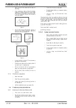
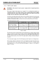
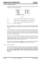
3.1.1  If the victim is not responsive

Follow the A-B-C’s of basic life support.

• 

Place  victim  flat  on  his  backon  a  hard 

surface.

• 

Open airway: lift up neck, push forehead back 
(

Figure 1

). 

Figure 1

Содержание PJ500C-LCD

Страница 1: ...PJ500C LCD PJ1000 LIGHT User Manual Volume 1 Manufactured by Italy...

Страница 2: ...bound in Italy No part of this manual may be reproduced memorized or transmitted in any form or by any means electronic or mechanic including photocopying recording or by any informa tion storage and...

Страница 3: ...nd Rear Panel Description 20 6 1 Front Panel 20 6 2 Rear Panel 21 6 3 Connectors description 22 7 Technical Specifications 23 8 Operating principles 24 8 1 Power supply 24 8 2 Interface board SL010IN3...

Страница 4: ...PJ500C LCD PJ1000 LIGHT ii User Manual Rev 1 0 15 12 06 This page was intentionally left blank...

Страница 5: ...incidental defects 5 Re shipment costs or insurance of the unit or replacement units parts Any damage to the goods must be reported to the carrier in writing on the shipment receipt Any discrepancy or...

Страница 6: ...ment of electrical Burns 3 2 1 Extensive burned and broken skin Cover area with clean sheet or cloth Do not break blisters remove tissue remove adhered particles of clothing or apply any salve or oint...

Страница 7: ...0C LCD e PJ1000 LIGHT are compact design and user friendliness Another key feature is its modular concept design the different functions are performed by modules with most connections achieved through...

Страница 8: ...are is based on a menu system User has four navigation buttons available to browse submenus ESC and ENTER The rear panel features the mains input connectors with a mains voltage switch chap 6 2 to sel...

Страница 9: ...s and capabilities Please see the relevant sections for additional details IMPORTANT When configuring and testing the transmitter in which the amplifier is integrated be sure to have the Final Test Ta...

Страница 10: ...re used PJ500C LCD 230 Vac 115 Vac PJ1000 light 230 Vac 115 Vac Main Power Supply fig 6 2 item 7 e 20 2x 25A type 10x38 2x 25A type 10x38 Service power supply fig 6 2 item 19 1x 1A type 5x20 1x 2A typ...

Страница 11: ...RF output see figure 6 2 to an adequately rated dummy load or to the antenna WARNING Electric shock hazard Never handle the RF output connector when the machine is powered on and no load is connected...

Страница 12: ...FF and output power set to upper limit unless otherwise specified by customer 5 1 2 Pilot exciter setup Set up the pilot exciter so that the output power it delivers to a matched load equals the maxim...

Страница 13: ...wer check and setup Go to Pwr menu figure 5 2 menu 5 and look up forward output power Fwd reflected power Rfl and input power Inp readings With drive power set as specified in the Final Test Table amp...

Страница 14: ...power reading on the display will be 0 zero whereas the SET bar which you can control using the keys provides a graphic display of the amount of power that will be delivered the moment you switch back...

Страница 15: ...is Menu 2 Next to SET indication a bar provides a graphic display of preset output power The filled portion of the bar is proportional to set power level Example 100 output power Full bar 1000W in out...

Страница 16: ...er never exceed the specified power rating NOTE Exciter drive power setting should never exceed 20W or it will trigger an Overdrive Alarm NOTE If power is set to 0 W in the edit mode the INTERLOCK OUT...

Страница 17: ...Screen Power Setup Menu Default Menu Figure 5 2 When the display is off touching any key will turn on backlighting When the display is on pressing the ESC button chap 6 1 from the default menu menu 1...

Страница 18: ...achine operation In the LOCAL mode the machine can read and modify its operating parameters through the navigation keys and the management firmware whereas all other sources are locked out In the REMO...

Страница 19: ...setting go to the default menu menu 1 as outlined earlier 5 4 3 Power Amplifier P A Menu This screen is made up of four lines that can be scrolled using the buttons and shows the readings relating to...

Страница 20: ...s the cause for the stop chap 5 3 4 1 After 15 seconds the machine attempts to re start if a new alarm condition is detected cycle is repeated over and over again up to 10 times maximum If machine re...

Страница 21: ...r threshold exceeded Alarm 3 Monitoring cycle is as follows An alarm condition occurs Alarm is displayed and device is locked out for 15 sec Operating conditions are restored Verification Upon reachin...

Страница 22: ...control mode press Reset Alm in the alarm menu menu 7 or power off and back on again using the POWER switch chap 6 2 Machine set to REMOTE control mode power off and back on again sending the appropr...

Страница 23: ...ess becomes significant when the exciter is connected in an RVR transmission system that uses this protocol Do not change it unless strictly required 5 4 6 Version Menu Vrs This screen holds machine v...

Страница 24: ...an external interlock signal 5 CONTRAST Display contrast trimmer 6 ESC Press this button to exit a menu 7 Navigation button used to browse menu system and edit parameters 8 Navigation button used to b...

Страница 25: ...INTERLOCK OUT Interlock output BNC connector when the transmitter goes into stand by mode the normally floating central connector is connected to ground 11 SERVICE DB9 connector for factory setting 1...

Страница 26: ...for power limitation AGC 3 GND Ground 4 SDA IIC I O Serial for IIC communication 5 VPA Tlm ANL OUT PA supply voltage 3 9V F S 6 FWD Tlm ANL OUT Forward power 3 9V F S 7 Power Good DIG OUT Signalling...

Страница 27: ...onnector DB9 F DB9 F Factory reserved for firmware program I2 Cbus Connector Modem Connector RS485 Serial Interface Connector Remote Interface Connector DB15F DB15F IIC 5 analog digital inputs 5 analo...

Страница 28: ...SURGE PROT PFC or RECTIFIER LED CARD R F INPUT R F OUTPUT RF MODULES MAINS R F 2 X R F 2 X R F R F DC 2 X 50VDC 2 X VPA 50VDC 2 X VPA 50VDC FWD PWR RFL PWR BIAS PS ALARM VOLTAGE REG SERVICES PS 3 dB A...

Страница 29: ...commodates a bank of surge arresters that protect the machine from any surge events in the power mains Mains voltage is brought from this module to the main Power switch on the front panel figure 6 1...

Страница 30: ...rforms the following tasks It uses AC voltage from transformer TR1 to generate and distribute service power supply over the panel board It controls and provides interfacing of the mains surge protecti...

Страница 31: ...tter Splitter Board code SLSITEX500L1 for PJ500C LCD or SLSPLTEX1KL1 for PJ1000 LIGHT splits the incoming power input signal equally to all RF modules The combiner Combiner Board code SLCOTEX500L1 for...

Страница 32: ...Ext AGC RFL Temperature too high Any one RF module drawing too much current 8 8 External Telemetry Interface Board SLTLMTXLCD03 This board provides an I O interface for the CPU with the outside envir...

Страница 33: ...us components pointed out 1 2 3 4 5 6 7 8 9 10 11 12 13 14 15 Figure 9 1 1 Bias Board SLBIAS1K3U 2 2 Pass through Filter Board SLFILPJ1KM 3 Low Pass Filter Board SLLPFTEX1KL 4 Panel Board SL007PC2002...

Страница 34: ...m View PJ500C LCD The figure below shows the equipment bottom view with the various components pointed out Figure 9 2 1 Filter PS Board SLFILPSPJ1KC 2 LED PS Board SLLEDPSTEX1K 3 Interface Board SL010...

Страница 35: ...rd SLFILPJ1KM 3 Low Pass Filter Board SLLPFTEX1KL 4 Panel Board SL007PC2002 5 FAN1 Cooling Fan VTL4184 6 Power Factor Correction Board PFCPSL1000 7 50V 34A Power Supply PSL5034 8 Pulse Protection Boar...

Страница 36: ...View PJ1000 LIGHT The figure below shows the equipment bottom view with the various components pointed out Figure 9 4 1 Filter PS Board SLFILPSPJ1KC 2 LED PS Board SLLEDPSTEX1K 3 Interface Board SL01...

Отзывы: