background image


APEX1930 USER

 MANUAL V1.0.00                                                    Tech Support: 1-888-317-8766 

17


In the above page, you can set device time and update time-related information. 


5.4.2. Network Set-up 


<Network Set-ups> 

¾


SYSTEM 


Cascade Code: 

Type the pre-assigned cascade code. Otherwise, you cannot access the 

system setup. 

• Location Information: 

Enter the latitude and longitude. You can input values either in 

Decimal Degrees or Degrees-Minutes-Seconds. 
  [Example] 
    (‘N/S’ | ‘E/W’) ddd.dddddd: (Latitude: N 39.006967 Longitude: W 94.532306) 

 Refresh Time: 

Set each refresh time for connecting to Local port and Remote port. 


¾


ETHERNET SETTING 

• 

Ethernet IP Mode/IP Address:

 Enables you to set a connection mode for the network 

connected to the APEX1930 remote LAN port. When you “select” Auto, the device 
automatically assigns the IP address. When you select “Static”, it is possible to set an IP 
address of your choosing. 

• 

SNMP:

 In order to send Heartbeat and alarm related information to a remote monitoring 

server, you can set a server IP address. The factory default IP address is 10.22.25.15. 

• 

Heartbeat Interval: 

Sets the time to transmit the Heartbeat to the NMC Server. 

Содержание APEX 1930

Страница 1: ...APEX 1930 PCS Band Repeater User s Manual Please read this manual before operating this product After you finish reading this manual store it in a safe place for future reference...

Страница 2: ...ABLE INSTALLATION 11 4 1 CABLE CONNECTION 11 4 2 POWER ON 12 4 3 GROUNDING 13 5 GUI OPERATION 13 5 1 GUI OPERATION FLOW CHART 14 5 2 INTERNET NETWORK SETUP 14 5 2 1 Windows 7 14 5 3 GUI LOGIN 16 5 4 G...

Страница 3: ...ICATION ALARM 37 7 SPECIFICATIONS 39 7 1 RF CHARACTERISTICS 39 7 2 ENVIRONMENTAL SPECIFICATION 39 7 3 ELECTRONIC SPECIFICATION 40 7 4 MECHANICAL SPECIFICATION 40 8 APPENDIX 41 8 1 US PCS CHANNEL 41 8...

Страница 4: ...tron Inc Notice This document describes the specifications installation and operation of the APEX 1930 repeater Hardware and software mentioned in this document are subject to continuous development...

Страница 5: ...in very close proximity facing each other can lead to severe damage to the repeater RF EXPOSURE INFORMATION A minimum separation distance of 7 9 inches 20cm must be maintained between the user and th...

Страница 6: ...tion Reason 1 3 3 WEB GUI Version History List Revision History Approval Ver Issue Ver Date Item Description Reason 1 4 Glossary The following is a list of abbreviations and terms used in this manual...

Страница 7: ...D Automatic Shutdown ASD does not 1 prevent oscillation 2 protect from excessive input ASD helps protect the amplifier from over load ASD helps protect the network by preventing excessive signal outpu...

Страница 8: ...such as base station fringe areas business and industrial building etc APEX1930 receives signals from a base station amplifies and retransmits the signals to the mobile stations It also receives ampl...

Страница 9: ...igh performance User friendly design Local monitoring and control through the Web GUI interface Remote monitoring and control through the Web GUI interface Reports the status of connection as a functi...

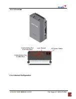
Страница 10: ...APEX1930 USER MANUAL V1 0 00 Tech Support 1 888 317 8766 7 2 4 1 Overview 2 4 2 Internal Configuration...

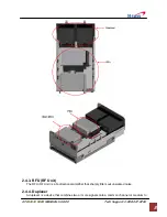
Страница 11: ...upport 1 888 317 8766 8 2 4 3 RFU RF Unit The RFU RF Unit is a bi directional amplifier that sharply filters out unwanted noise 2 4 4 Duplexer A duplexer is a device that combines two or more signals...

Страница 12: ...The AC DC adaptor supplies a steady DC power to the APEX1930 equipment by drawing power from the general in wall AC outlets 2 4 6 MCU Main Control Unit The MCU Main Control Unit is the control unit o...

Страница 13: ...ting Grounding RF Cable Connection Power On 3 1 Mounting Step 1 Drill holes directly through the template Attach the mounting bracket to the wall using provided bolts or extra screws Step 2 Lean the A...

Страница 14: ...pport 1 888 317 8766 11 Step 4 Example 4 Cable Installation 4 1 Cable Connection Step 1 Connect a cable from the donor antenna to the Donor Antenna Port Step 2 Connect a cable from a repeater s servic...

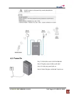
Страница 15: ...00 Tech Support 1 888 317 8766 12 4 2 Power On Step 1 Connect the power cord to the Repeater Step 2 Plug the power cord into a wall outlet Step 3 Turn the red power button on Step 4 Check if the gree...

Страница 16: ...uilding ground Step 2 Connect the ground cable to the rod 5 GUI Operation APEX1930 operates on a customer provided PC based platform with the following system requirements Windows XP or Windows Vista...

Страница 17: ...lable Maximum Gain You can see system operating and alarm information on Status page 3 AGC control AGC automatically assigns gain 4 Manual Control Gain value setting by User Setting in order to acquir...

Страница 18: ...ng Center Step 4 Click View status of Local Area Connection Step 5 Click Properties and a caution pop up window will appear Click OK Step 6 Select Internet Protocol Version 4 TCP IPv4 and click Proper...

Страница 19: ...irm a User ID and type the password into the password box Type operator for the password and then click OK Step 3 The pop up message for the login success will appear Click OK Step 4 When the login pr...

Страница 20: ...9 006967 Longitude W 94 532306 Refresh Time Set each refresh time for connecting to Local port and Remote port ETHERNET SETTING Ethernet IP Mode IP Address Enables you to set a connection mode for the...

Отзывы: